You will apply the following boundary conditions and load to the hinge model:
A boundary condition called Fixed that constrains all degrees of freedom at the end of the hinge piece with the lubrication hole, as shown in Figure C–40.
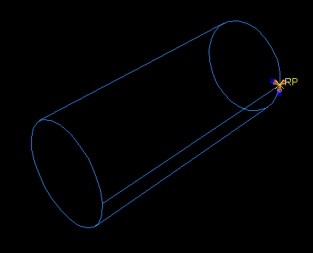
A boundary condition called NoSlip that constrains all degrees of freedom of the pin while contact is established during the first analysis step. You will modify this boundary condition in the second analysis step (the step in which the load is applied) so that degrees of freedom 1 and 5 are unconstrained. Figure C–41 illustrates this boundary condition applied at the reference point.
A boundary condition called Constrain that constrains all degrees of freedom of a point on the solid hinge piece during the first analysis step. You will modify this boundary condition in the second analysis step so that degree of freedom 1 is unconstrained when the load is applied.
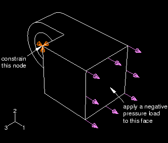
A load called Pressure that you apply to the end of the solid hinge piece during the second analysis step. Figure C–42 illustrates the constraint and the pressure load applied to the solid hinge.
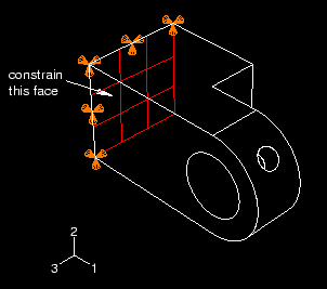
You will apply a boundary condition to the face at the end of the hinge piece with the lubrication hole to fix the hinge piece in place during the analysis.
To constrain the hinge piece with the lubrication hole:
In the Model Tree, click mouse button 3 on the BCs container and select Manager from the menu that appears.
The Boundary Condition Manager dialog box appears.
In the Boundary Condition Manager, click Create.
The Create Boundary Condition dialog box appears.
In the Create Boundary Condition dialog box:
Name the boundary condition Fixed.
Accept Initial from the list of steps.
Accept Mechanical as the default Category selection.
Select Displacement/Rotation as the type of boundary condition for the selected step.
Click Continue.
The Region Selection dialog box appears.
From the right side of the prompt area, click Select in Viewport to select the object directly from the viewport.
The Region Selection dialog box closes.
Select the gridded face shown in Figure C–43 as the region where the boundary condition will be applied.
By default, ABAQUS/CAE selects only objects that are closest to the front of the screen, and you cannot select the desired face unless you rotate the hinge. However, you can use the selection options to change this behavior.From the prompt area, click the selection options tool ![]() .
.
From the Options dialog box that appears, toggle off the closest object tool ![]() .
.
Click over the desired face.
ABAQUS/CAE displays Next, Previous, and OK buttons in the prompt area.
Click Next and Previous until the desired face is highlighted.
Click OK to confirm your choice.
Click mouse button 2 to indicate that you have finished selecting regions.
The Edit Boundary Condition dialog box appears. The selection options return to the default setting of selecting only objects that are closest to the front of the screen.
In the dialog box:
Toggle on the buttons labeled U1, U2, and U3 to constrain the end of the hinge in the 1-, 2-, and 3-directions. You do not need to constrain the rotational degrees of freedom of the hinge because solid elements (which have only translational degrees of freedom) will be used to mesh the hinge.
Click OK to close the dialog box.
The boundary condition that you just created appears in the Boundary Condition Manager, and arrows appear on the nodes of the face indicating the constrained degrees of freedom. The Boundary Condition Manager shows that the boundary condition remains active in all steps of the analysis.
Tip: You can suppress the display of boundary condition arrows in the same way that you suppress the visibility of part instances. Click the BC tab in the Assembly Display Options dialog box to see the boundary condition display options.
In the first general step of the analysis you will establish contact between the two hinge pieces and between the hinge pieces and the pin. To fix the pin during this step, you must apply a boundary condition to the pin that constrains all its degrees of freedom.
To apply a boundary condition to the pin:
In the Boundary Condition Manager, click Create.
The Create Boundary Condition dialog box appears.
In the Create Boundary Condition dialog box:
Name the boundary condition NoSlip.
Accept Initial in the Step text field.
Accept Mechanical as the default Category selection.
Select Displacement/Rotation as the type of boundary condition for the selected step.
Click Continue.
In the viewport, select the rigid body reference point on the pin as the region where the boundary condition will be applied.
Click mouse button 2 to indicate that you have finished selecting regions.
The Edit Boundary Condition dialog box appears.
In the dialog box:
Toggle on all the buttons to constrain all the degrees of freedom of the pin.
Click OK.
The new boundary condition appears in the Boundary Condition Manager.
Objects that you can create and modify in certain steps—such as boundary conditions, loads, and interactions—have special managers that allow you to modify objects and change their status in different analysis steps.
In this section you will use the boundary condition manager to modify the boundary condition NoSlip so that translation in the 1-direction and rotation about the 2-axis are unconstrained during the loading step.
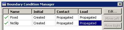
Currently the Boundary Condition Manager displays the names of the two boundary conditions that you have created as well as their status in each step: both boundary conditions are Created in the initial step and Propagated through the following analysis steps.
To modify a boundary condition:
In the Boundary Condition Manager, click the cell labeled Propagated that lies in the row labeled NoSlip and in the column labeled Load, as shown in Figure C–44.
That cell becomes highlighted.
On the right side of the manager, click Edit to indicate that you want to edit the NoSlip boundary condition in the Load step.
The Edit Boundary Condition dialog box appears, and ABAQUS/CAE displays a set of arrows on the model indicating where the boundary condition is applied and which degrees of freedom are constrained.
In the editor, toggle off the buttons labeled U1 and UR2 so that the pin is allowed to translate in the 1-direction and rotate about the 2-axis. Click OK to close the dialog box.
In the Boundary Condition Manager, the status of the NoSlip boundary condition in the Load step changes to Modified.
In the first analysis step, in which contact is established, you will constrain a single node of the solid hinge piece in all directions. These constraints, along with contact with the pin, are enough to prevent rigid body motion of the solid piece. In the second analysis step, in which the load is applied to the model, you will remove the constraint in the 1-direction.
To constrain the solid hinge piece:
Create a displacement boundary condition in the Initial step, and call it Constrain.
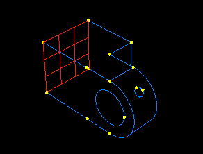
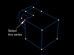
Apply the boundary condition to the vertex selected from the solid hinge piece, as shown in Figure C–45.
Constrain the vertex in the 1-, 2-, and 3-directions.
In the Load step, modify the boundary condition so that the hinge is unconstrained in the 1-direction.
When you have finished creating boundary conditions, click Dismiss to close the Boundary Condition Manager.
Next, you apply a pressure load to the face at the end of the solid hinge. You apply the load in the 1-direction during the second analysis step.
To apply a load to the solid hinge:
In the Model Tree, double-click the Loads container to create a new load.
The Create Load dialog box appears.
In the Create Load dialog box:
Name the load Pressure.
Accept Load as the default selection in the Step text field.
From the Category list, accept Mechanical as the default selection.
From the Types for Selected Step list, select Pressure.
Click Continue.
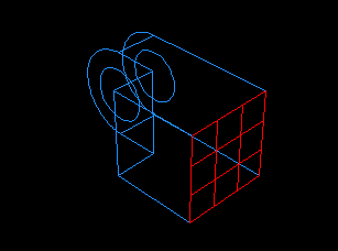
In the viewport, select the face at the end of the solid hinge piece as the surface to which the load will be applied, as shown by the gridded surface in Figure C–46.
Click mouse button 2 to indicate that you have finished selecting regions.
The Edit Load dialog box appears.
In the dialog box, enter a magnitude of –1.E6 for the load, and click OK.
Arrows appear on the face indicating the applied load. The arrows are pointing out of the face because you applied a negative pressure.