Products: ABAQUS/Standard ABAQUS/Design
Many industries use centrifuges to separate out contaminants during purification processes. Efficiency of the purification process is directly related to the speed of rotation. Consequently, the centrifuge chamber is designed to be stiff to maintain its shape and lightweight to reduce self-stressing due to centrifugal loads. This example uses the design sensitivity analysis capability in ABAQUS/Design to examine how the key structural responses depend on design parameters such as the thicknesses of composite laminae, the layup angles, the density of the centrifuge end plates, and geometric imperfections.
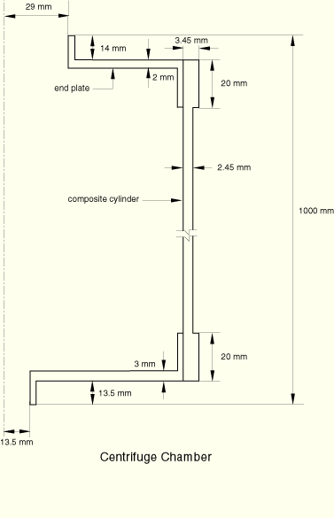
The centrifuge depicted in Figure 11.2.1–1 consists of a composite centrifuge chamber and aluminum end plates. The centrifuge chamber is a cylinder 970 mm long and 175 mm in diameter. It spins about its axis at 10000 rpm. The cylinder is a filament-wound composite (hybrid) laminate with a balanced layup. The laminate layup is (![]() ), where 0° represents the layup of the fibers along the length of the cylinder and
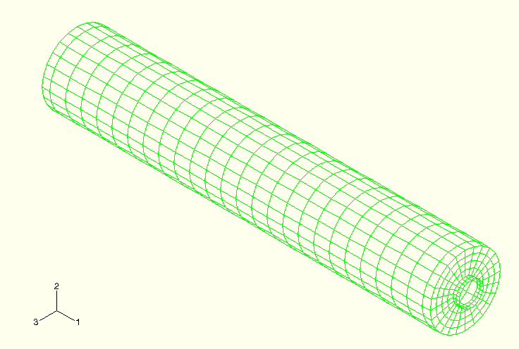
), where 0° represents the layup of the fibers along the length of the cylinder and ![]() = 45° is the angle of the helical layers. The axial (0°) and helical layers have a thickness of 0.15 mm and 0.5 mm, respectively. Aluminum alloy end plates are bonded at both ends of the cylinder. The lower plate provides an attachment point for a magnetic bearing, while the top plate supports the magnet of the inductance drive. In the region where the cylinder meets the end plates an additional circumferential (90°) outer layer of 1 mm thickness is added to the laminate. The centrifuge is modeled using reduced-integration, 4-node shell (S4R) elements. The mesh is shown in Figure 11.2.1–2. All the displacements on the perimeter of the end plate lip are constrained at one end of the cylinder, and only the radial displacements are constrained at the other end; thus, the centrifuge is allowed to change length freely in the axial direction under loading. A static analysis with centrifugal loading is performed.
= 45° is the angle of the helical layers. The axial (0°) and helical layers have a thickness of 0.15 mm and 0.5 mm, respectively. Aluminum alloy end plates are bonded at both ends of the cylinder. The lower plate provides an attachment point for a magnetic bearing, while the top plate supports the magnet of the inductance drive. In the region where the cylinder meets the end plates an additional circumferential (90°) outer layer of 1 mm thickness is added to the laminate. The centrifuge is modeled using reduced-integration, 4-node shell (S4R) elements. The mesh is shown in Figure 11.2.1–2. All the displacements on the perimeter of the end plate lip are constrained at one end of the cylinder, and only the radial displacements are constrained at the other end; thus, the centrifuge is allowed to change length freely in the axial direction under loading. A static analysis with centrifugal loading is performed.
A T800 carbon fiber material is used in the 0° and 90° layers, and a HM400 material is used in the helical layers. The density of both materials is 1600 kg/m3. The material properties for the composites are given in Table 11.2.1–1. The aluminum alloy has a Young's modulus of E = 70 GPa, a Poisson's ratio of ![]() = 0.33, and a density of
= 0.33, and a density of ![]() = 2800 kg/m3.
= 2800 kg/m3.
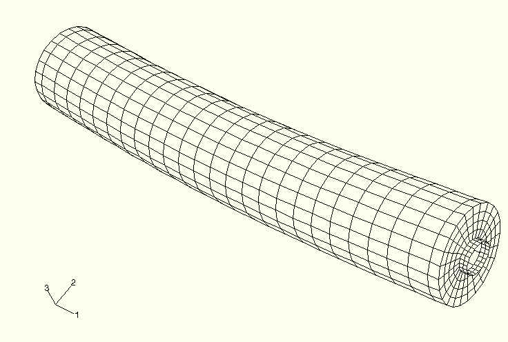
The design parameters are thickness of the helical layer (THM400), thickness of the axial layer (TT800), and angle of the helical layer (THETA). Because of the high speed of rotation of the centrifuge, geometric imperfections can have a significant effect on the displacements and stresses. To study this effect, an imperfection in the form of the first bending mode of the centrifuge is used; the magnitude of the imperfection, ALPHA, is chosen as a shape design parameter. An imperfection in the form of a bending mode is chosen because the maximum attainable rotation speed is known to be well-predicted by the natural frequency of the first bending mode of the centrifuge. The gradients of the nodal coordinates with respect to ALPHA required to carry out the sensitivity analysis are obtained from a *FREQUENCY analysis. Figure 11.2.1–3 shows the first bending mode of the centrifuge. Though bending predominates in this mode, there is also a small twisting component.
All plotted sensitivity results are normalized to enable comparison between the parameters. The normalization is carried out by multiplying the response sensitivity by the value of the parameter and dividing by the maximum value of the response. For example, the sensitivity of the stress component S11 with respect to the design parameter THM400 is normalized by first multiplying the sensitivity by the value of the THM400 parameter and then dividing by the maximum S11 value found in the model. For the shape design parameter ALPHA an estimated imperfection of 0.1% of the total length of the cylinder (ALPHA = 1 mm) is used while computing the normalized sensitivities.
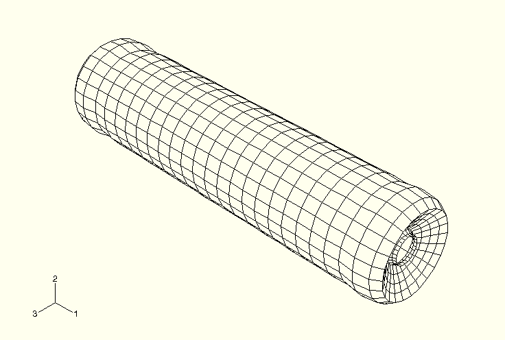
Figure 11.2.1–4 shows the deformed shape of the centrifuge at 10000 rpm. The centrifuge contracts in the axial direction and bulges outward radially. Because of the lap joint where the composite cylinder meets the end plate, some bending is seen at both ends.
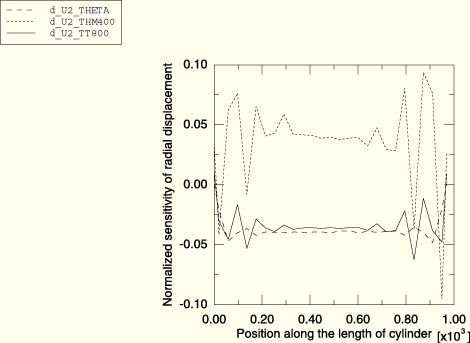
The normalized sensitivity of the radial displacement along the length of the composite cylinder (between the two end plates) is plotted in Figure 11.2.1–5 for all the design parameters except the shape design parameter. The plot shows that the radial displacement has negative sensitivity to THETA and TT800. An increase in the layup angle of the helical layer or an increase in the thickness of the axial layers will stiffen the cylinder and reduce the radial displacement. The positive sensitivity of the radial displacement to THM400 indicates that the added self-induced centrifugal load due to the increase in the mass of the helical layers will more than negate any advantage gained in the stiffness.
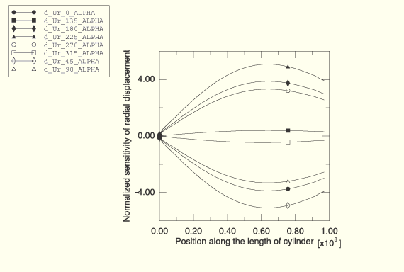
Figure 11.2.1–6 plots the sensitivity of the radial displacement to the shape design parameter ALPHA. Since the sensitivity is not axisymmetric for this design parameter, it is plotted for every meridian in 45° increments counterclockwise around the circumference beginning at the 1–2 plane. The radial displacement sensitivities are obtained from the global Cartesian displacement sensitivities output by ABAQUS via a two-dimensional vector transformation at each meridional position. The largest sensitivities in Figure 11.2.1–6 are almost two orders of magnitude higher than those observed in Figure 11.2.1–5. This means that the geometric imperfections have a relatively large effect on the radial displacement and that the centrifuge manufacturing process must have a tight tolerance on axial shape imperfections.
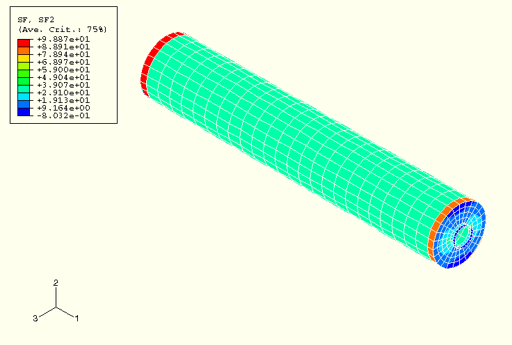
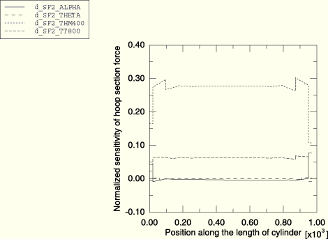
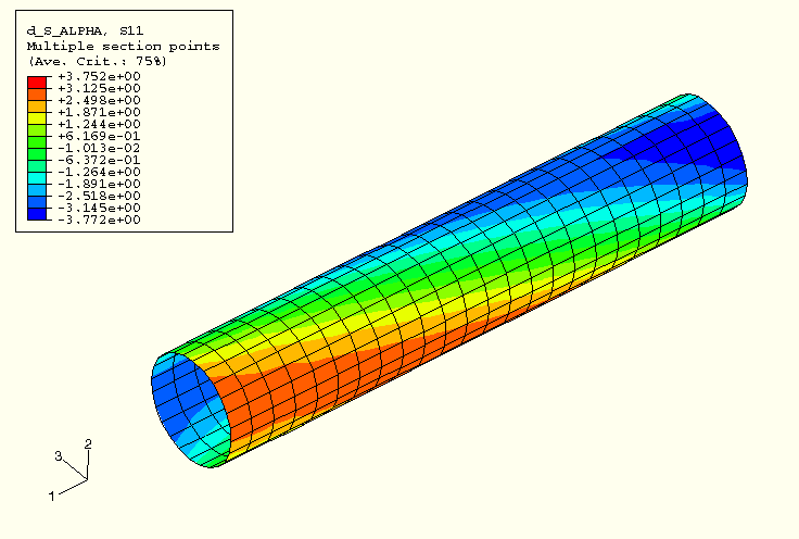
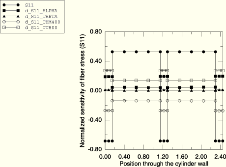
The dominant section force in the structure is in the hoop direction of the cylinder. Figure 11.2.1–7 shows the contour plot of section force in the hoop direction, and Figure 11.2.1–8 shows the normalized sensitivities of section force in the hoop direction plotted as a function of the position along the length of the cylinder. As expected, only the design parameters that affect the mass (TT800 and THM400) have nonzero sensitivities with THM400 being more sensitive because of its larger thickness. As the centrifuge is allowed to contract freely in the axial direction, the net section force in the axial direction is zero. However, the stresses in the axial direction are not zero. Figure 11.2.1–9 shows the contour plot of the sensitivity of the fiber stress (S11) in the helical layer with respect to the shape design parameter. To understand in detail how the stresses in the laminate are affected by the design parameters, normalized sensitivities of the fiber stress (S11) through the thickness of the cylinder wall at a point midway along the length of the cylinder are plotted in Figure 11.2.1–10. S11 through the thickness of the wall is also plotted after dividing it by the maximum value of S11 in the model. The plot shows that the axial layers are under compression and the helical layers are under tension. S11 has positive sensitivity to TT800: increasing the thickness of the axial layers will reduce the compressive stress in the axial layers and increase the tensile stress in the helical layers. S11 has negative sensitivity to THM400: increasing the thickness of the helical layers will reduce the stress in the helical layers and increase the stress in the axial layers. Increasing the angle of the helical layers will reduce the stress in the axial layers since S11 in the axial layers has a small positive sensitivity to THETA. The sensitivity of S11 to ALPHA is analogous to the sensitivity of the radial displacement to ALPHA around the circumference of the cylinder.
The sensitivities can be used to compute the change that would be required in the design parameters to achieve a particular change in response or to assess the change in the response that would result from a change in the design parameters. Consider, for example, the following objectives: (a) to reduce the compressive stress in the axial layer by 10% and (b) to determine the maximum compressive stress in the axial layer caused by a specified magnitude of the shape imperfection (![]() ALPHA = 0.6).
ALPHA = 0.6).
The compressive fiber stress in the axial layer is 26.38 MPa. Figure 11.2.1–10 indicates that the most effective way to achieve the desired reduction is to increase the thickness of the axial layer. The required increase is given by
![]()
The maximum compressive stress in the axial layer caused by the specified shape imperfection can be obtained from
![]()
Frequency analysis of the centrifuge.
Sensitivity analysis of the centrifuge subjected to centrifugal loads.