Product: ABAQUS/Standard
This example illustrates the effect of coupling between a structure and an acoustic medium. Such coupling problems arise when the solid-fluid interaction is fundamental to the overall vibrational behavior of the body or of the acoustic fluid. Typical examples of such problems include loudspeaker enclosures, fluid-filled tanks, muffler systems, and vehicle cabin enclosures. The basis of the coupled acoustic/structural vibration capability in ABAQUS is described in “Coupled acoustic-structural medium analysis,” Section 2.9.1 of the ABAQUS Theory Manual.
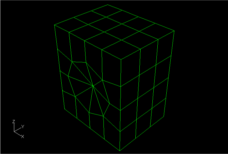
The model is shown in Figure 8.1.2–1. The system considered here consists of a speaker box, a speaker cone, and the interacting interior. To simplify the problem, the effect of interacting air at the outside of the speaker box is neglected. The width, depth, and height of the speaker box are 0.5 m, 0.4 m, and 0.6 m, respectively. Its thickness is 0.015 m. The speaker box is made of wood with a Young's modulus, E, of 11.6 GPa; a Poisson's ratio, ![]() , of 0.3; and a density,
, of 0.3; and a density, ![]() , of 562 kg/m3. At the center of the front speaker box, there is a cone-shaped speaker 0.345 m in diameter, 0.04 m in height, and 0.0001 m in thickness. No mass or impedance of the speaker is considered. The speaker is made of polyethylene with a Young's modulus, E, of 3.4 GPa; a Poisson's ratio,
, of 562 kg/m3. At the center of the front speaker box, there is a cone-shaped speaker 0.345 m in diameter, 0.04 m in height, and 0.0001 m in thickness. No mass or impedance of the speaker is considered. The speaker is made of polyethylene with a Young's modulus, E, of 3.4 GPa; a Poisson's ratio, ![]() , of 0.3; and a density,
, of 0.3; and a density, ![]() , of 450 kg/m3. The air has a density,
, of 450 kg/m3. The air has a density, ![]() , of 1.11 kg/m3 and a bulk modulus,
, of 1.11 kg/m3 and a bulk modulus, ![]() , of 0.134 MPa. Volumetric drag of the air is assumed to have a negligible effect in this problem, so it is ignored in this analysis.
, of 0.134 MPa. Volumetric drag of the air is assumed to have a negligible effect in this problem, so it is ignored in this analysis.
First-order hexahedral acoustic elements (AC3D8) and first-order acoustic triangular prism elements (AC3D6) are used to fill in the volume of the interior air region. The speaker box and speaker are meshed with S4R and S3R elements, respectively. No mesh convergence study has been done since the example is intended only as an illustration. The choice of mesh density (element size) is discussed in “Acoustic, shock, and coupled acoustic-structural analysis,” Section 6.9.1 of the ABAQUS Analysis User's Manual.
The surface-based contact approach is used. Surfaces are defined at the inside of the speaker box and the speaker cone and at the free surface of the air. The *TIE option is used to couple the structure with the inside air. To constrain the structure, four corner points of the bottom panel are simply supported.
A substructure analysis is perfomed as well. The entire speaker model is turned into a coupled structural-acoustic substructure using 150 extracted eigenmodes. A substructure load case is generated to be used in the forced response analyses.
The results for each of the analyses are discussed below.
If the eigenvalues of the structure alone or the acoustic medium alone are not in the range of interest, it is not necessary to consider the whole system simultaneously. Thus, it is recommended to understand the modal characteristics of each part separately before analyzing the whole system. The *FREQUENCY procedure takes acoustic-structural coupling effects into account by default if an acoustic medium and a structure are joined by the *TIE option or by ASI-type elements. To ignore this effect, set the ACOUSTIC COUPLING parameter equal to OFF on the *FREQUENCY option or remove the *TIE interaction.
The results of the natural frequency analysis of the uncoupled system are summarized in Table 8.1.2–1. The natural frequencies for both the structure and the air span the same range in this example, which shows that the two parts can affect each other. Thus, the coupled approach should be adopted to understand the characteristics of the whole speaker system in this example.
Table 8.1.2–2 shows the results of the natural frequency analysis of the coupled system. Due to the coupling effect, the eigenfrequencies shift mode by mode. Each mode shape is also more complex than those in the uncoupled case, so that each mode has nonzero components on both the structural and acoustic parts. The substructure analysis yields eigenfrequencies identical to those from the analysis without substructures.
The response of the system is obtained by using mode-based, direct-solution, or subspace-based steady-state dynamic analysis. If mode-based or subspace-based steady-state dynamic analysis is used, a *FREQUENCY step should be performed prior to the *STEADY STATE DYNAMICS step. Coupled analyses are performed as frequency sweeps from 300–400 Hz. The system is excited by a concentrated force at node 83 (at the center point of the speaker cone), whose magnitude is 1.0 N in phase and 0.06 N out of phase. The *STEADY STATE DYNAMICS, DIRECT and *STEADY STATE DYNAMICS, SUBSPACE PROJECTION=ALL FREQUENCIES results for the coupled system are shown in Figure 8.1.2–2. This figure illustrates the acoustic pressure at the center point of the speaker cone, plotted as a function of frequency. The results for the mode-based steady-state dynamic analysis (not shown) are identical to those for the subspace-based analysis. The substructure analysis produces results that are virtually identical to the results from the equivalent analysis without substructures. The effect of the air on the structural response is revealed when the optional ACOUSTIC COUPLING parameter is set equal to OFF on the *FREQUENCY option. As shown in this figure, the effect of coupling is quite significant since both the structure and the acoustic medium have several natural frequencies in this region. The response peaks correspond to the coupled modes 4, 6, and 7 computed in the *FREQUENCY step. The transient dynamic response of the system to a concentrated force is also computed using the *DYNAMIC and *MODAL DYNAMIC analyses types. The responses computed with the two options compare well.
Natural frequency extraction for coupled system, subspace projection, and direct steady-state dynamics.
Natural frequency extraction for uncoupled system and subspace projection steady-state dynamics.
Natural frequency extraction for coupled, implicit dynamic time integration and modal dynamic time integration.
Substructure generation for the coupled structural-acoustic model.
*STEADY STATE DYNAMICS analyses using the substructure.
Equivalent *STEADY STATE DYNAMICS analysis without substructures.
Table 8.1.2–1 Uncoupled frequency analysis.
| Mode | Frequency, Hz | Description |
|---|---|---|
| 1 | 0 | Air: constant pressure |
| 2 | 285.13 | Air: z-direction |
| 3 | 293.88 | Structure: y-direction |
| 4 | 315.12 | Structure: z-direction |
| 5 | 340.14 | Air: x-direction |
| 6 | 346.14 | Structure: front and rear panel |
| 7 | 422.52 | Air: y-direction |
| 8 | 431.81 | Air: skew-symmetric mode in x–z plane |
| 9 | 450.26 | Structure |
| 10 | 466.58 | Structure |