Product: ABAQUS/Standard
This example illustrates the use of connector elements to model a Geneva mechanism, which converts continuous rotary motion into intermittent rotary motion.
The Geneva mechanism is essentially a timing device. It is used in counting instruments and other applications where a continuous rotary motion needs to be converted to an intermittent rotary motion. For example, it is used in clocks to limit the number of winding rotations of the clock spring and in movie film projectors to move the film frame by frame. The Geneva mechanism consists of a rotating body with a protruding pin and another rotating body with slots into which the pin slides.
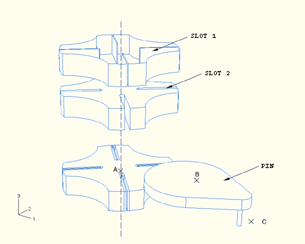
In this example problem the mechanism consists of three bodies named PIN, SLOT1, and SLOT2, as illustrated in Figure 4.1.8–1. SLOT1 is an analytical rigid surface that overlays SLOT2. SLOT2 is modeled as a display body. SLOT1 and SLOT2 are rigidly joined to each other at point A so as to allow them to rotate in unison about A. SLOT2 has a radius of 3.0 units and is 1.0 units thick. The pin is constrained to be rigid. The thickness of the rigid part of PIN is 0.5 units. The rigid portion of PIN has a reference point B, and PIN is allowed to rotate about B. Distance AB is 4.24264 units in the model. The protruding portion of PIN is located at a distance of 3.0 units from reference point B, and its length is 1.0 units. The rigid portion of PIN has a radius of 3.0 units.
The contact between PIN and SLOT1 takes place through a single slave node located at C, the center of the protruding portion of PIN. As a result, the slots in SLOT1 (used for contact evaluation) are 0.05 units wide, whereas the slots in SLOT2 (used for display purposes only) are 0.25 units wide. The slots have a length of about 2.0 units to allow for the pin to slide. This contact is considered to be frictionless.
All the degrees of freedom at A and B, except the rotational degrees of freedom about the 3-axis, are fixed. A rotation of 720 degrees about the 3-axis is prescribed at B over three steps.
An EULER connector is constructed connecting A, the reference point of SLOT1, to the ground. The *CONNECTOR DAMPING and *CONNECTOR FRICTION options are used to introduce damping and friction in the EULER connector. Damping and friction will prevent rigid body motion of SLOT1 and SLOT2 after the pin has left the slot.
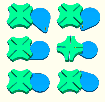
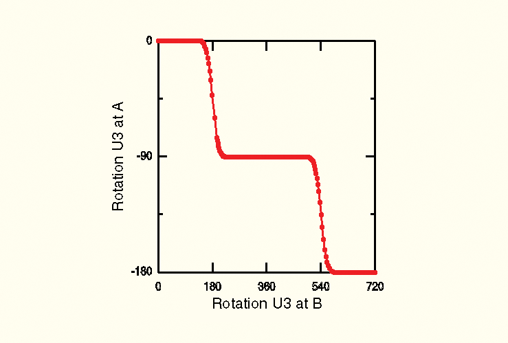
The protruding portion of PIN enters the slots in SLOT1 as PIN is rotated. This interaction between PIN and SLOT1 results in the rotation of SLOT1 and SLOT2, and they rotate 90 degrees for every complete 360 degree rotation of PIN. Figure 4.1.8–2 shows the configuration of the bodies of the Geneva mechanism at some intermediate instants during the analysis. Figure 4.1.8–3 shows a plot of the U3 rotation of SLOT1 at A as a function of the U3 rotation of PIN at B.
Python replay file for constructing the Geneva mechanism model in ABAQUS/CAE.
Geneva mechanism model.