Products: ABAQUS/Standard ABAQUS/Explicit
This example illustrates the use of connector elements to model a three-dimensional trailing edge mechanism.
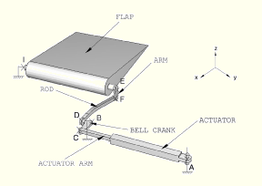
The complete model of the flap is shown in Figure 4.1.4–1. An actuator rotates a bell crank through the deployment of an actuator arm. The bell crank pushes and pulls a connecting rod that attaches to the arm of the flap.
The flap is connected to a rigid shaft on the aircraft wing structure at points E and I. An arm on the shaft is attached to the rod at point F. The other end of the rod attaches to a bell crank at point D. The bell crank is attached to the airplane so that it can rotate about point B. The axis of rotation of the bell crank passes through point B and is parallel to the global Z-axis. The rotation of the bell crank is driven by the deployment of the actuator arm. The actuator system attaches to the bell crank at point C. The other end of the actuator system is attached to the aircarft structure at point A and is allowed to compensate for the change of angle caused by the rotation of the bell crank.
A load is applied at the center of gravity of the flap so that it is colinear and oriented along the global Z-axis.
The bodies named in Figure 4.1.4–1 are connected as follows:
ACTUATOR is connected to the ground at point A using a HINGE connector element. ACTUATOR and ACTUATOR ARM are connected using a TRANSLATOR connector element. The *CONNECTOR MOTION option is used to modify the configuration of the actuator system as a function of time.
BELL CRANK is physically attached to the ground with a hinge connection at point B. The axis of rotation of the hinge connection is parallel to the global Z-axis. However, using a HINGE connector element to attach BELL CRANK to the ground would overconstrain the model. Because of the connections used between point A and point C, point C is already constrained to travel in the global X–Y plane. Because the position of point B has to remain fixed in space, the rotation of BELL CRANK about the ![]() -axis is already constrained. As a result, only three translations and the rotation of BELL CRANK about the
-axis is already constrained. As a result, only three translations and the rotation of BELL CRANK about the ![]() -axis need to be constrained to realize the hinge connection. BELL CRANK is, thus, attached to the ground using JOIN and UNIVERSAL connector elements at point B. The UNIVERSAL connection is used to constrain the relative rotation of BELL CRANK with respect to the ground about the
-axis need to be constrained to realize the hinge connection. BELL CRANK is, thus, attached to the ground using JOIN and UNIVERSAL connector elements at point B. The UNIVERSAL connection is used to constrain the relative rotation of BELL CRANK with respect to the ground about the ![]() -axis.
-axis.
ROD is connected to BELL CRANK at point D and to ARM at point F using JOIN connector elements. A CARDAN connector element is added at point F between ROD and ARM to introduce an elastic behavior to prevent the free rotation of ROD around its axis.
FLAP and ARM are connected by a WELD connector element at point E. FLAP is attached to the ground using a HINGE connection at point I.
All bodies in the model are visualized using display bodies connected to the relevant connector nodes. Separate models in ABAQUS/Standard and ABAQUS/Explicit include friction, plasticity, and damage in the connectors.
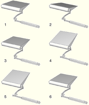
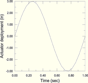
The amplitude curve used to drive the deployment of the actuator arm is shown in Figure 4.1.4–3. Figure 4.1.4–2 shows the configuration of the flap mechanism at intermediate instants as it is actuated. As the actuator system is deployed, the flap rotates around the ![]() -axis to modify the aerodynamics of the wing.
-axis to modify the aerodynamics of the wing.
Python replay file for constructing the flap mechanism model in ABAQUS/CAE.
ABAQUS/Standard flap mechanism model.
ABAQUS/Standard flap mechanism model with friction.
ABAQUS/Explicit flap mechanism model with friction.
ABAQUS/Standard flap mechanism model with plasticity.
ABAQUS/Explicit flap mechanism model with plasticity.
ABAQUS/Explicit flap mechanism model with plasticity and damage.