Product: ABAQUS/Standard
This example illustrates the use of the co-simulation capability to perform fluid-structure interaction (FSI) simulation modeling the effect of air venting an automotive car door seal during closure. Higher fidelity results for the door closure force are obtained by modeling the air escaping the vented seal. Since the air cannot escape instantaneously, there is a transient pressure build up in the seal cavity resisting the closure of the door. The collapse of the door seal is modeled using ABAQUS. The air escaping the vented seal is modeled using FLUENT. MpCCI is used to couple the ABAQUS and FLUENT simulations in a staggered manner.
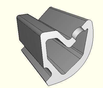
Automotive car door seals generally are hollow extruded sections of elastomeric material that line the perimeter of the door frame. When the door is closed, the seals act to keep water and other material from the environment out of the car, as well as providing some damping for the vibration motion of the door. A secondary role of the door seal is to provide damping resistance to the door as it is closed. In this role the seal can have a significant impact on the character of the door closing behavior, minimizing harshness and providing a quality closing sound. One variable that seal designers consider in controlling this door closing behavior is the spacing of the vents. Air contained in the seal interior needs to escape during the closure. If insufficient vents are provided, the internal pressure build up due to the collapsing volume of the seal cavity may prevent proper closure of the door.
The model consists of two domains. The structural domain, which consists of the seal and door, is modeled using ABAQUS/Standard. The fluid domain, which consists of the air inside the seal section and in the vent hole, is modeled using FLUENT. The structural and fluid domains share a common interface across which the interface loads and boundary conditions are exchanged.
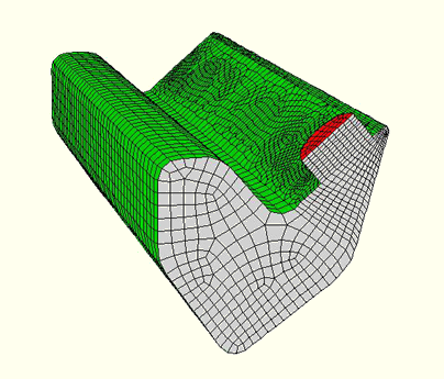
The structural domain is modeled as a three-dimensional periodic section, as shown in Figure 2.3.1–2. The modeled seal section is 50 mm long, with a vent hole 5 mm in diameter positioned at one end. The seal is meshed with C3D8I elements. The car door is modeled with an analytical surface-based rigid body. The seal material is elastic, with a Young's modulus of 60.7 MPa and a Poisson's ratio of 0.4.
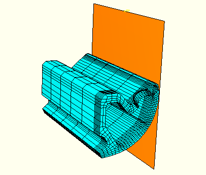
The fluid domain is modeled with a hexahedral mesh, as shown in Figure 2.3.1–3. The air has a density of 1.225 kg/m3 and a viscosity of 1.7894 10–6 kg/ms. Laminar flow is used for the fluid domain. Since large-scale deformation of the fluid boundary is expected, the FLUENT moving-deforming-mesh feature is used to update the fluid mesh. Refer to the FLUENT case file for additional details of the solver and moving-deforming-mesh settings for this example.
The ABAQUS and FLUENT models each have loads and boundary conditions that are applied to regions unique to their respective domains and that do not affect the other model directly. They are applied without regard to the intent to perform a co-simulation analysis and represent the loads and boundary conditions one might apply to perform an uncoupled analysis. A second category of loads and boundary conditions occur at the common interface of the fluid and structural domains, where the two models must exchange loads and/or boundary conditions for the staggered solution.
The left surface of the seal is fixed, representing adhesion of the surface to the door frame. Symmetry conditions are applied at both ends of the section, resulting in a model of a seal with a vent-hole pitch of 100 mm. A finite-sliding contact interface is defined between the seal outer surface and the door rigid body. The door rigid body has an initial prescribed velocity of 0.25 m/s into the seal, and this velocity is ramped off to zero over a period of 28 ms.
The fluid domain has an initial pressure of zero. A zero-pressure boundary condition is applied at the outlet, and symmetry boundary conditions are applied at both ends. The air flow is initiated through the collapse of the seal.
The interior wall of the seal, including the interior of the vent hole, of the ABAQUS model is identified as an FSI-interface region, and is paired with the exterior region (zone) of the air domain, including the interior of the vent hole, of the FLUENT model.
At this interface FLUENT sends concentrated forces representing the internal pressure due to the collapsing seal to ABAQUS, and ABAQUS sends the current geometry of the surface to FLUENT.
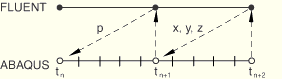
ABAQUS and FLUENT are configured to communicate results using a fixed coupling step size with a period of 10–5 s. Each code also has a nominal time increment of 10–5 s. Automatic time incrementation is used in ABAQUS; that is, ABAQUS may subcycle, take one or more increments, between the coupling steps. This is important so that ABAQUS can resolve the contact conditions appropriately. A serial (or Gauss-Seidel type) coupling scheme is employed as illustrated in Figure 2.3.1–4. ABAQUS is selected to lead the exchange in this simulation since the airflow is initiated due the collapse of the seal.
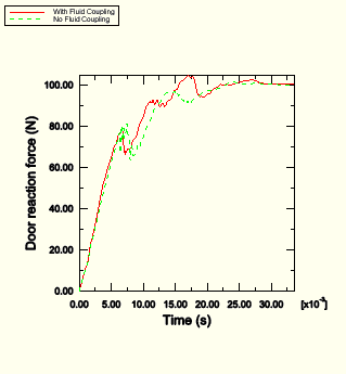
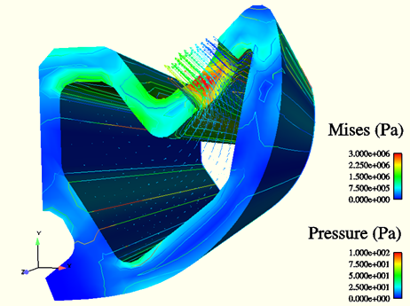
The result of interest in this simulation is the reaction force on the car door, which is obtained for both the coupled FSI simulation and for an ABAQUS-only simulation in which the flow of air is ignored. The simulation is run for 120% of the duration of the closing, or 33.6 ms. A comparison of the reaction force results is shown in Figure 2.3.1–5. A composite view of the seal and fluid at a time of 7 ms is shown in Figure 2.3.1–6. The reaction force plot clearly shows differences, although minor, in the force history due to the effect air in the seal; this effect will vary based on the door closing velocity, the seal geometry, the spacing of the vents, and the elastomeric properties.
To run the co-simulation using the MpCCI project file:
The ABAQUS, FLUENT, and MpCCI input files should be copied to the appropriate product directories where the codes are executed: problemDir/ABAQUS, problemDir/FLUENT, problemDir/MpCCI.
From the problemDir/MpCCI directory, submit the MpCCI GUI project file in batch mode:
mpcci –batch fsi_doorseal.csp
The MpCCI configuration file is also included so that these problems can be run without the MpCCI GUI.
Door seal closure model without co-simulation.
Door seal closure model with co-simulation.
MpCCI configuration file.
MpCCI GUI project file for UNIX and Linux platforms.
MpCCI GUI project file for Windows platforms.
FLUENT case file.