Product: ABAQUS/Explicit
This problem illustrates the following concepts: large deformation kinematics, equations of state, elastic-plastic material, transformations, detonation points.
The units used in this analysis are referred to as c.g.![]() sec. Using these units, length is given in centimeters (cm), mass in grams (gm), and time is measured in microseconds (
sec. Using these units, length is given in centimeters (cm), mass in grams (gm), and time is measured in microseconds (![]() sec). The stresses have units of mega bars (M bar). These units are commonly used in shock wave physics applications because the pressures tend to have values on the order of unity.
sec). The stresses have units of mega bars (M bar). These units are commonly used in shock wave physics applications because the pressures tend to have values on the order of unity.
In this example problem two concentric pipes have the annulus between them filled with high explosive (HE). The inside radius of the inner pipe is 10 mm. The inside radius of the outer pipe is 20 mm. Both pipes are steel with a wall thickness of 2 mm. Each pipe is modeled with 6 elements in the radial direction, while the HE is modeled with 24 elements in the radial direction.
The steel pipe is an elastic, perfectly plastic material with Young's modulus of 221.1 GPa (2.211 M bar), Poisson's ratio of 0.279, yield strength of 430 MPa (.0043 M bar), and density of 7846 kg/m3 (7.846gm/cm3).
The explosive material is modeled using the JWL equation of state with detonation wave speed = 7596 m/sec (.7596 cm/microsecond), A = 520.6 GPa (5.206 M bar), B = 5.3 GPa (0.053 M bar), R1 = 4.1, R2 = 1.2, ![]() = .35, density = 1900 kg/m3 (1.9 gm/cm3), and initial specific energy = 3.63 Joule/kg (0.0363 T erg/gm). The tension cutoff pressure is assumed to be zero and is specified using the *TENSILE FAILURE option. Refer to “Equation of state,” Section 17.9.1 of the ABAQUS Analysis User's Manual, for a description of this material model.
= .35, density = 1900 kg/m3 (1.9 gm/cm3), and initial specific energy = 3.63 Joule/kg (0.0363 T erg/gm). The tension cutoff pressure is assumed to be zero and is specified using the *TENSILE FAILURE option. Refer to “Equation of state,” Section 17.9.1 of the ABAQUS Analysis User's Manual, for a description of this material model.
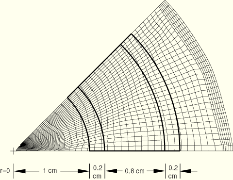
The explosive material is detonated at four points around the circumference of the cylinder. Because of the symmetry in this problem, only one-eighth of the pipe is modeled. Figure 2.1.8–1 shows the original geometry and the location of the detonation point for the model. A transformed coordinate system is used to define the symmetry conditions along the sloping boundary. The interface between the explosive material and the steel is modeled with NO SEPARATION contact that allows for relative slip without separation between the two materials.
This analysis is run in two steps to reduce the amount of output written to the output database file. In the early part of the analysis, the deformations are not of much interest. Hence, the first step has a duration of 6 ![]() sec. After 6
sec. After 6 ![]() sec the deformations are becoming significant. The second step has a duration of 1.5
sec the deformations are becoming significant. The second step has a duration of 1.5 ![]() sec.
sec.
This analysis is run as both a two-dimensional case using CPE4R elements and as a three-dimensional case using C3D8R elements. In the three-dimensional case the displacements are constrained to be zero in the out-of-plane direction.
Figure 2.1.8–2 through Figure 2.1.8–5 show a sequence of the deformed shapes computed by ABAQUS/Explicit for the two-dimensional case. The undeformed configuration is shown superimposed on the deformed shapes. Although not shown here, the results of the three-dimensional analysis are indistinguishable from those of the two-dimensional analysis.
This problem tests the features listed, but it does not provide independent verification of them.