Product: ABAQUS/Standard
This example demonstrates the use of automatic techniques to stabilize unstable static problems. Geometrically nonlinear static problems can become unstable for a variety of reasons. Instability may occur in contact problems, either because of chattering or because contact intended to prevent rigid body motions is not established initially. Localized instabilities can also occur; they can be either geometrical, such as local buckling, or material, such as material softening.
This problem models the thermal forming of a metal sheet; the shape of the die may make it difficult to place the undeformed sheet exactly in initial contact, in which case the initial rigid body motion prevention algorithm is useful. Metal forming problems are characterized by relatively simply shaped parts being deformed by relatively complex-shaped dies. The initial placement of the workpiece on a die or the initial placement of a second die may not be a trivial geometrical exercise for an engineer modeling the forming process. ABAQUS accepts initial penetrations in contact pairs and instantaneously tries to resolve them; as long as the geometry allows for this to happen without excessive deformation, the misplacement of the workpiece usually does not cause problems. On the other hand, if the workpiece is initially placed away from the dies, serious problems may arise. Unless there are enough boundary conditions applied, singular finite element systems of equations result because one or more of the bodies has free rigid body motions. This typically arises when the deformation is applied through loads instead of boundary conditions. It is possible to eliminate this problem by modifying the model, which can be cumbersome for the analyst. Alternatively, the *CONTACT CONTROLS, APPROACH option allows initial placement of a body apart from others with smooth load-controlled motion until contact gets established.
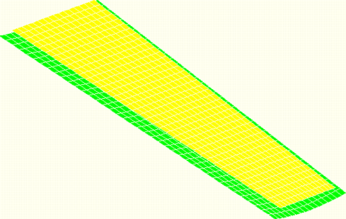
This example looks at the thermal forming of an aluminum sheet. The deformation is produced by applying pressure and gravity loads to push the sheet against a sculptured die. The deformation is initially elastic. Through heating, the yield stress of the material is lowered until permanent plastic deformations are produced. Subsequently, the assembly is cooled and the pressure loads are removed, leaving a formed part with some springback. Although the sheet is initially flat, the geometrical nature of the die makes it difficult to determine the exact location of the sheet when it is placed on the die. Therefore, an initial gap between the two bodies is modeled, as shown in Figure 1.3.17–1.
The model consists of a trapezoidal sheet 10.0 m (394.0 in) long, tapering from 2.0 m (78.75 in) to 3.0 m (118.0 in) wide, and 10.0 mm (0.4 in) thick. The die is a ruled surface controlled by two circles of radii 13.0 m (517.0 in) and 6.0 m (242.0 in) and dimensions slightly larger than the sheet. The sheet is initially placed over 0.2 m (7.9 in) apart from the die. The sheet has a longitudinal symmetry boundary condition, and one node prevents the remaining nodes from experiencing in-plane rigid body motion. The die is fixed throughout the analysis. The sheet mesh consists of 640 S4R shell elements, while the die is represented by 640 R3D4 rigid elements. The material is an aluminum alloy with a flow stress of 1.0 × 10⁸ Pa (14.5 ksi) at room temperature. A flow stress of 1.0 × 10³ Pa (0.15 psi) at 400°C is also provided, essentially declaring that at the higher temperature the material will flow plastically at any stress. A Coulomb friction coefficient of 0.1 is used to model the interaction between the sheet and die.
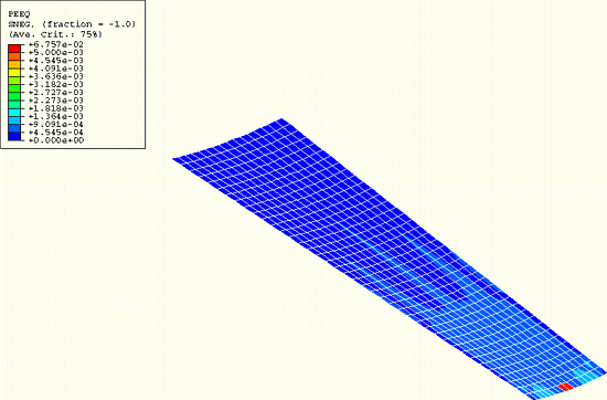
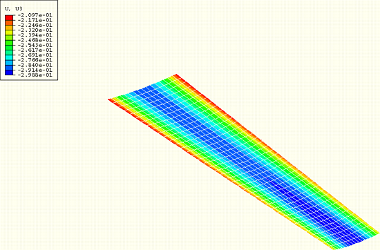
The analysis consists of three steps. In the first step a gravity load and a pressure load of 1.0 × 10⁵ Pa (14.5 psi) are applied, both pushing the sheet against the die. This step is aided by the automatic contact approach procedure to prevent unrestrained motion of the sheet. This procedure consists of the application of viscous pressure along the contact direction (normal to the die), opposing the relative motion between the sheet and the die. During the first increment of the step ABAQUS applies a very high amount of damping so that it can judge the magnitude of the external loads being applied, as well as determine the initial distances between the slave and master surfaces. Based on the results of this initial attempt a suitable damping coefficient is calculated and the increment is repeated, such that a smooth approach is produced during the initial part of the step. In this particular case five increments take place before the first contact point closes; from then on the sheet is pressed against the die. As soon as contact is established, the relative velocities between the sheet and the die decrease and become almost zero at the end of the step, which essentially eliminates the damping forces. In addition, ABAQUS ramps down the damping coefficient to zero from the middle of the step on. This guarantees that the viscous forces decrease to zero, thus avoiding any discontinuity in the forces at the start of the next step. The shape and relatively low curvatures of the die are such that the deformation at the end of the step is elastic (Figure 1.3.17–2). In the second step a two-hour heating (from room temperature to 360°C) and cooling (back to 50°C) cycle is applied to the loaded assembly. As a result of the decrease in flow stress permanent (plastic) deformation develops, as shown in Figure 1.3.17–3. Finally, in the third step the pressure load is removed and the springback of the deformed sheet is calculated, as depicted in Figure 1.3.17–4.
ABAQUS would like to thank British Aerospace Airbus, Ltd. for providing the basic data from which this example was derived.
Thermal forming model.
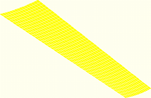
Thermal forming model with surface-to-surface contact.