Product: ABAQUS/Standard
Seals are common structural components that often require design analyses. ABAQUS can be used to perform nonlinear finite element analyses of seals and provide information needed to determine the seal performance. Information such as a load-deflection curve, seal deformation and stresses, and contact pressure distribution is readily obtained in these analyses. ABAQUS allows for pressure penetration effects between the seal and the contacting surfaces to be considered in these analyses, making routine analyses of seals more realistic and accurate. Analyses of clutch seals, threaded connectors, car door seals, and air duct kiss seals are some applications where pressure penetration effects are important.
The surface-based pressure penetration capability is used to simulate pressure penetration between contacting surfaces. It is invoked by using the *PRESSURE PENETRATION option, which is described in “Pressure penetration loading,” Section 30.1.7 of the ABAQUS Analysis User's Manual. This capability is provided for simulating cases where a joint between two deforming bodies (for example, between two components threaded onto each other) or between a deforming body and a rigid surface (such as a soft gasket used in a joint) is exposed at one or multiple ends to a fluid or air pressure. This air pressure will penetrate into the joint and load the surfaces forming the joint until some area of the surfaces is reached where the contact pressure between the abutting surfaces exceeds the critical value specified on the *PRESSURE PENETRATION option, cutting off further penetration.
The major consideration in an air duct kiss seal design is to provide sealing while avoiding excessive closure force. A poorly designed air duct seal that minimizes the amount of effort to close the fan cowl door may fail to prevent leakage and reduce wind noise. The model used in this example is a simplified version of an air duct kiss seal. It illustrates how pressure penetration effects can be modeled using ABAQUS.
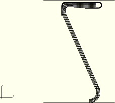
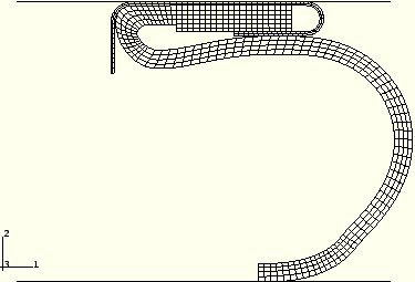
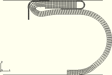
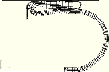
The seal modeled is a rolled shape seal. An axisymmetric model of the seal is developed, as shown in Figure 1.1.15–1. The top horizontal rigid surface represents the air fan cowl door, and the bottom horizontal rigid surface represents the seal groove. The rolled seal is 2.54 mm (0.1 in) thick and 74.66 mm (2.9 in) high; and its inner diameters at the top and bottom surfaces are 508.5 mm (20 in) and 528.3 mm (20.8 in), respectively. A folded metal clip is partially bonded to the top surface of the seal. The thickness of the metal clip is 0.48 mm (0.019 in).
The material of the seal is taken to be an incompressible rubberlike material. To obtain the material constants, the Ogden form of the strain energy function with ![]() 4 is used to fit the uniaxial test data. The metal clip is made of steel, with a Young's modulus of 206.8 GPa (3.0 × 10⁷ lb/in2) and a Poisson's ratio of 0.3. CAX4H elements are used to model the seal and the metal clip. The contact pair approach is used to model the contact between the top surface of the metal clip and the top rigid surface representing the fan cowl door, where the pressure penetration is likely to occur. The contact pair approach is also used to model the contact between the seal and the bottom rigid surface, the contact between the seal and the unbonded portion of the metal clip, and the self contact of the seal. The mechanical interaction between the contact surfaces is assumed to be frictional contact. Therefore, the *FRICTION option is used to specify friction coefficients. To increase computational efficiency, the SLIP TOLERANCE parameter on the *FRICTION option is used for the contact surfaces between the seal and the metal clip because the dimensions of these elements vary greatly. Fixed boundary conditions are applied initially to the reference node of the top rigid surface, 5001, and the reference node of the bottom rigid surface, 5002. The vertical edge at the bottom of the seal is constrained such that it cannot be moved in the 1-direction. The bottom node of the vertical edge, 1, touches the bottom rigid surface and is held fixed in the 2-direction. The top rigid surface is located initially 1.27 mm (0.05 in) above the top surface of the metal clip.
4 is used to fit the uniaxial test data. The metal clip is made of steel, with a Young's modulus of 206.8 GPa (3.0 × 10⁷ lb/in2) and a Poisson's ratio of 0.3. CAX4H elements are used to model the seal and the metal clip. The contact pair approach is used to model the contact between the top surface of the metal clip and the top rigid surface representing the fan cowl door, where the pressure penetration is likely to occur. The contact pair approach is also used to model the contact between the seal and the bottom rigid surface, the contact between the seal and the unbonded portion of the metal clip, and the self contact of the seal. The mechanical interaction between the contact surfaces is assumed to be frictional contact. Therefore, the *FRICTION option is used to specify friction coefficients. To increase computational efficiency, the SLIP TOLERANCE parameter on the *FRICTION option is used for the contact surfaces between the seal and the metal clip because the dimensions of these elements vary greatly. Fixed boundary conditions are applied initially to the reference node of the top rigid surface, 5001, and the reference node of the bottom rigid surface, 5002. The vertical edge at the bottom of the seal is constrained such that it cannot be moved in the 1-direction. The bottom node of the vertical edge, 1, touches the bottom rigid surface and is held fixed in the 2-direction. The top rigid surface is located initially 1.27 mm (0.05 in) above the top surface of the metal clip.
The seal and the unbonded portion of the clip are loaded by air pressure on all of their inner surfaces and by contact pressure generated by closing the air fan cowl door. Two nonlinear static steps, all of which include large-displacement effects, are used to simulate these loading conditions.
In the first step the top rigid surface moves 35.56 mm (1.4 in) downward in the y-direction, simulating the closing of the fan cowl door.
In the second step the inner surface of the seal is subjected to a uniform air pressure load of 206.8 KPa (30.0 lb/in2) since some gaps between the seal and the top rigid surface have been closed. The pressure penetration is simulated between the top surface of the metal clip (PPRES), which includes 31 elements, and the top rigid surface (CFACE). Air pressure penetration does not need to be modeled between the metal clip and the seal because they are well bonded.
The *PRESSURE PENETRATION option is invoked to define the node exposed to the air pressure, the magnitude of the air pressure, and the critical contact pressure. The surface PPRES is exposed to the air pressure at node 597, with a pressure magnitude of 206.8 KPa (30.0 lb/in2). A default value of zero for the critical contact pressure is used, indicating that the pressure penetration occurs only when contact at a slave node is lost.
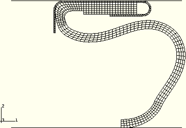
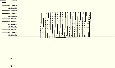
The deformed configuration and the contours of the contact pressures on the seal at the end of Step 1 are shown in Figure 1.1.15–2 and Figure 1.1.15–3. A nonuniform contact pressure is observed along the surface of the seal. The contact pressure at the first five slave nodes is zero.
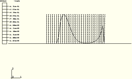
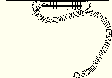
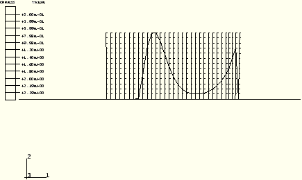
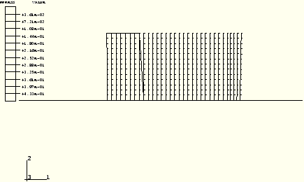
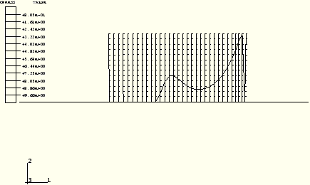
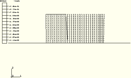
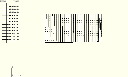
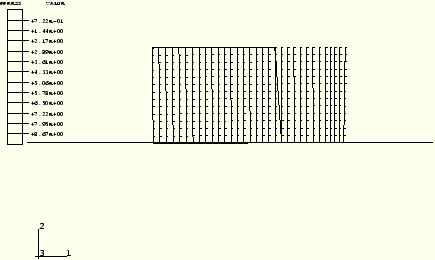
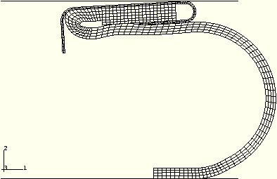
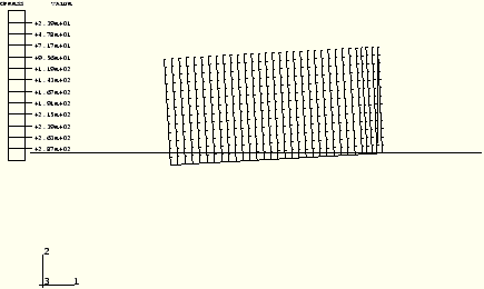
The penetrating pressure loads are applied during Step 2. The air pressure is applied immediately to elements associated with the first five slave nodes since the contact pressure there is zero and the pressure penetration criterion is satisfied. The spread of the penetration is captured in Figure 1.1.15–4 through Figure 1.1.15–12, which show the deformed seal, the contact pressure profile, and the air pressure profile corresponding to load increments 2, 8, and 12 of Step 2. The pressures applied to the surface corresponding to these three increments are 3.23 KPa (0.469 lb/in2), 23.37 KPa (3.39 lb/in2), and 64.74 KPa (9.39 lb/in2), respectively.
Increased penetrating pressure loads applied in Step 2 further reduce the contact pressure, eventually causing complete air penetration through the seal. The seal was lifted off from the air fan cowl door except at the last slave node, 663, where the contact pressure is well-maintained due to imposed boundary conditions and the air pressures. The development of the weakening of the sealing is captured in Figure 1.1.15–13 through Figure 1.1.15–16, which show the deformed seal and the contact pressure profile corresponding to load increments 14 and at the end of Step 2. The pressures applied to the surface corresponding to these two increments are 85.5 KPa (12.4 lb/in2) and 206.8 KPa (30.0 lb/in2), respectively.
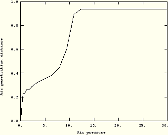
The behavior of the seal throughout the loading histories can be best described by plotting the air penetration distance as a function of the air pressure, as shown in Figure 1.1.15–17. It is clear that air penetration into the seal accelerates only when the pressure is on the order of 65.5 KPa (9.5 lb/in2). The air completely penetrates through the seal when the pressure is 82.7 KPa (12.0 lb/in2), which is approximately equal to 80% of the sea level atmospheric pressure.
Pressure penetration simulation of an air duct kiss seal.
Node definitions for the seal model.
Element definitions for the metal part of the seal model.
Element definitions for the rubber part of the seal model.