The following examples create three buttons, one at a time, using the default layout hints. As each button is created, the figures show the effect on the space remaining in the layout cavity.
Example 1
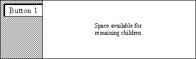
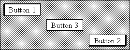
The first example starts by creating a single button on the left side of the cavity. The default value for the vertical position is LAYOUT_TOP, so the example places the button on the left side and at the top of the available space.
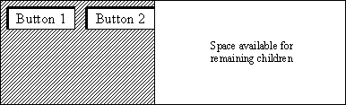
gb = FXGroupBox(parent, '') FXButton(gb, 'Button 1', opts=LAYOUT_SIDE_LEFT|BUTTON_NORMAL)The following statement adds a second button on the left side at the top of the available space:
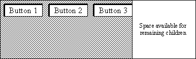
FXButton(gb, 'Button 2', opts=LAYOUT_SIDE_LEFT|BUTTON_NORMAL)The following statement adds a third button on the left side at the top of the available space:
FXButton(gb, 'Button 3',
    opts=LAYOUT_SIDE_LEFT|BUTTON_NORMAL)
Figure 4–11 shows the final configuration of the three buttons.Example 2
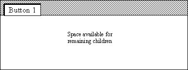
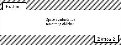
The second example illustrates how you can use nondefault layout hints. The example starts by using the default hints to position a button on top of the available space and on the left.
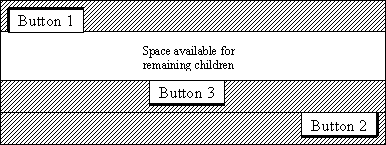
gb = FXGroupBox(p,'') FXButton(gb,'Button 1')The example then positions a second button on the right side on the bottom of the layout cavity.
FXButton(gb, 'Button 2',
opts=LAYOUT_SIDE_BOTTOM|LAYOUT_RIGHT|BUTTON_NORMAL) Finally, the example places a third button on the bottom of the available space and centered in the X-direction.FXButton(gb, 'Button 3',
opts=LAYOUT_SIDE_BOTTOM|LAYOUT_CENTER_X|BUTTON_NORMAL)Figure 4–15 shows the final configuration of the three buttons.