Product: ABAQUS/Explicit

This section verifies the rigid body dynamic behavior predicted with ABAQUS/Explicit by comparison with analytical solutions. Figure 1.3.7–1 shows the geometry of the system considered. A single rigid body is under the action of two springs, with one attached to the rigid body and the other in contact with the rigid body. A point load is also applied to the rigid body. The rigid body is constrained at the reference node to undergo planar motion. Several two-dimensional and three-dimensional analyses based on this geometry are performed. For all cases a dummy continuum element is used to control the time incrementation.
In the first problem only rotation about the out-of-plane axis is allowed at the reference node and all the translational degrees of freedom are constrained. The inertial properties of the rigid body are represented with mass ![]() 20 and inertia about the axis normal to the plane of motion
20 and inertia about the axis normal to the plane of motion ![]() 65 at the reference node. The two springs each have a stiffness equal to 1.0 × 10⁶. The mass, m, where the spring node comes in contact with the rigid body, is 5. The force applied, F, is 1.0 × 10⁵. The initial angular velocity of the rigid body,
65 at the reference node. The two springs each have a stiffness equal to 1.0 × 10⁶. The mass, m, where the spring node comes in contact with the rigid body, is 5. The force applied, F, is 1.0 × 10⁵. The initial angular velocity of the rigid body, ![]() , is 10. The end of the spring that is in contact with the rigid body has an initial velocity such that contact is already established at time
, is 10. The end of the spring that is in contact with the rigid body has an initial velocity such that contact is already established at time ![]() 0. The various quantities above are in a consistent set of units.
0. The various quantities above are in a consistent set of units.
A variation of the first problem is considered (see Figure 1.3.7–2) in which the rigid body reference node location does not correspond to the center of mass of the rigid body. Point masses are specified on the rigid body surface nodes, ![]() 10,
10, ![]() 10 (in three dimensions the surface node masses are each 5 since there are twice as many surface nodes); and the rotary inertia and the mass elements at the reference node are removed. The magnitude of the point masses is chosen such that the moment of inertia of the rigid body about the location of the pin constraint is the same as in the original problem; thus, the analytical solution for the rotational response is also the same.
10 (in three dimensions the surface node masses are each 5 since there are twice as many surface nodes); and the rotary inertia and the mass elements at the reference node are removed. The magnitude of the point masses is chosen such that the moment of inertia of the rigid body about the location of the pin constraint is the same as in the original problem; thus, the analytical solution for the rotational response is also the same.
Another variation of the original problem considered here, shown in Figure 1.3.7–3, is to allow translation parallel to the spring elements in addition to the rotation about the out-of-plane axis. The force applied is changed to ![]() –1.0 × 10⁵; the initial angular velocity,
–1.0 × 10⁵; the initial angular velocity, ![]() , is 10; and the initial velocity,
, is 10; and the initial velocity, ![]() , is 15. The initial velocity for the spring node in contact is chosen such that contact is already established at time
, is 15. The initial velocity for the spring node in contact is chosen such that contact is already established at time ![]() 0.
0.
A final variation of the problem is obtained by replacing the mass element and inertia element specified at the reference node with the surface masses forming the problem shown in Figure 1.3.7–4. The analytical solutions for the two active degrees of freedom are not the same for the last two problems since the reference node is allowed to translate.
To verify the co-simulation capability using ABAQUS/Explicit and MADYMO, the problems shown in Figure 1.3.7–2 and Figure 1.3.7–4 are reconsidered with a spring and a point mass that are in contact with the rigid body moved from the ABAQUS model to the MADYMO model. The contact condition is now enforced by MADYMO as both programs exchange data every increment.

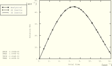
Figure 1.3.7–5 shows numerical solutions of the rotational response from the four analyses in which only rotation is allowed at the reference node and compares these solutions with a corresponding analytical solution based on the small-rotation assumption. For the problem shown in Figure 1.3.7–3 the rotational and translational solutions are compared with the analytical solutions in Figure 1.3.7–6 and Figure 1.3.7–7, respectively. Comparisons for the problem shown in Figure 1.3.7–4 are presented in Figure 1.3.7–8 and Figure 1.3.7–9. The results are in close agreement for all cases. The deviations from the analytical solutions observed in Figure 1.3.7–8 and Figure 1.3.7–9 as the analysis progresses are the result of effects from the observed large rotations, which are not accounted for in the analytical solution.
For the two co-simulation analyses performed using ABAQUS/Explicit and MADYMO, the results match the analytical solutions, shown in Figure 1.3.7–5, Figure 1.3.7–8, and Figure 1.3.7–9, fairly well.

Two-dimensional model with only a rotation active in the rigid body and a rotary inertia element at the reference node.
Two-dimensional model with one rotation and one translational degree of freedom active in the rigid body and a rotary inertia element at the reference node.
Similar to rbd_2d_i_xybc.inp but with the rigid body modeled using point masses distributed on the surface nodes.
Three-dimensional analysis similar to rbd_2d_i_xybc.inp.
Three-dimensional analysis similar to rbd_2d_i_xybc.inp but with the rigid body modeled using point masses distributed on the surface nodes.
A co-simulation analysis similar to rbd_3d_sm_xybc.inp but with a point mass and a spring in contact with the rigid body modeled in MADYMO.
Similar to rbd_2d_i_xbc.inp but with the rigid body modeled using point masses distributed on the surface nodes.
Three-dimensional analysis similar to rbd_2d_i_xbc.inp.
Three-dimensional analysis similar to rbd_2d_i_xbc.inp but with the rigid body modeled using point masses distributed on the surface nodes.
A co-simulation analysis similar to rbd_3d_sm_xbc.inp but with a point mass and a spring in contact with the rigid body modeled in MADYMO.
The MADYMO model used for co-simulation with the ABAQUS models am_a_rbd_3d_sm_xbc.inp and am_a_rbd_3d_sm_xybc.inp. It contains a point mass and a spring in contact with the rigid body modeled in ABAQUS.

Figure 1.3.7–1 Rigid body with an inertia element and having only rotation about the out-of-plane axis active at the reference node.
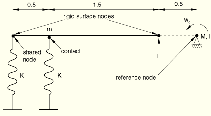
Figure 1.3.7–2 Rigid body with mass distributed at the surface nodes and having only rotation about the out-of-plane axis active at the reference node.
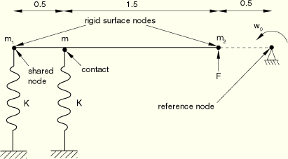
Figure 1.3.7–3 Rigid body with an inertia element and having one rotation and one translation active at the reference node.
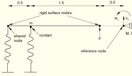
Figure 1.3.7–4 Rigid body with mass distributed at the surface nodes and having one rotation and one translation active at the reference node.
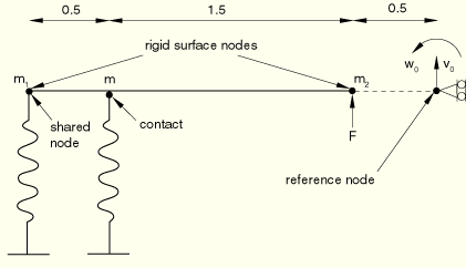
Figure 1.3.7–5 Predicted rigid body rotation compared with the analytical solution when only one rotational degree of freedom is active for the rigid body.
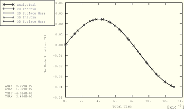
Figure 1.3.7–6 Predicted rigid body translation compared with the analytical solution when rotary inertia is specified and two degrees of freedom are active at the reference node.
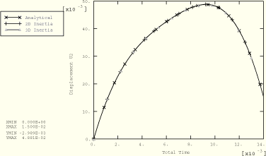
Figure 1.3.7–7 Predicted rigid body rotation compared with the analytical solution when rotary inertia is specified and two degrees of freedom are active at the reference node.
