You can use the Section Points dialog box to control the section points from which ABAQUS obtains integration point results and material orientations. Reinforcement (rebar) layers in membrane, shell, and surface elements are treated as section points for output purposes; each reinforcement layer has a unique name. For example, you can request results from the section points at the top surfaces of certain shells in the model, from the middle section points of certain beams in the model, or from a named reinforcement layer in certain membrane elements in the model.
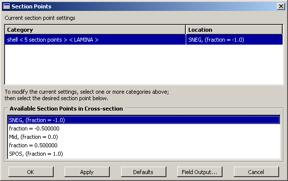
The Section Points dialog box is shown in Figure 24–1.
The Current section point settings field at the top of the dialog box displays a list of element categories. The elements within each category share common section properties, such as those listed below:
Section type.
Material name or composite specification.
Number of section points.
Cross-section geometry (beams only).
Element set associated with section.
The label for each category includes information about the section properties of the elements within the category. For example, the first category label that appears in the Category list in Figure 24–1 indicates the following:
The elements in this category are associated with a shell section.
The section definition includes the material A1.
The number of section points through the section is 5.
The Location list in the Current section point settings field displays the location of the section point from which output is currently displayed for each category. In many cases the location of a section point is described in terms of its position relative to the midpoint of the cross-section. For two-dimensional beams this relative position is reported as a fraction of the distance between the midpoint of the cross-section and the top or bottom surface of the section. For shells this relative position is reported as a fraction of the distance between the midpoint of the cross-section and the SPOS or SNEG surface of the section. Reinforcement layers are indicated by their unique name. A list of all of the available section point locations for the selected category appears in the Available Section Points in Cross-section field at the bottom of the dialog box.
For example, in Figure 24–1 the selected category contains a shell section with five section points. Therefore, the Available Section Points in Cross-section field contains a list of the five section point locations. The section point in the middle of the section is Mid, fraction = 0.0; the section point between the middle of the section and the SPOS surface is fraction = 0.5; the section point between the middle of the section and the SNEG surface is fraction = -0.5; and so on.
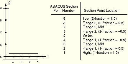
For beams with three-dimensional sections, the relative position of a section point can be reported as a fraction of the distance between the midpoint of the cross-section and
the top or bottom of the section (along the local 2-axis of the section) or
the left or right side of the section (along the local 1-axis of the section).
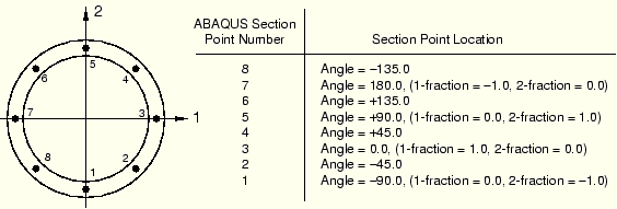
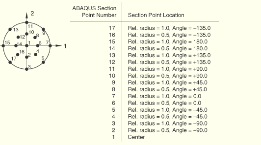
For more information about where section points are located in different section types, see the following:
To select the section point location of analysis results:
Locate the Section Points dialog box.
From the main menu bar, select Result![]() Section Points.
Section Points.
The Section Points dialog box appears.
In the Category field of the dialog box, select the element category or categories for which you want to change the output location.
The Available Section Points in Cross-section field in the bottom half of the dialog box changes to list the locations of the section points from which output was saved for the category you have selected. If you have selected more than one category, only those locations that are common to all of the selected categories appear in the list.
In the Available Section Points in Cross-section field, select the section point location of your choice.
The location listed for the selected categories in the Current section point settings field changes to reflect your selection.
In the Section Points dialog box, click OK to apply your settings and to exit the dialog box.
The model plot in the current viewport changes to display values from the specified section points. The plot legend, if active, changes to identify the specified section points. For information about the plot legend, see “Customizing the legend,” Section 38.1.
Results for subsequent contour, symbol, and material orientation plots; tabular reports; model probing; and X–Y data objects along a path will be obtained from the section points you have specified.