Product: ABAQUS/Standard

Frame in a plane: ![]() ,
, ![]() (Direction cosines of the normal are not used; any values given are ignored.)
(Direction cosines of the normal are not used; any values given are ignored.)
Frame in space: ![]() ,
, ![]() ,
, ![]() (Direction cosines of the normal are not used; any values given are ignored.)
(Direction cosines of the normal are not used; any values given are ignored.)

Local orientations defined as described in “Orientations,” Section 2.2.5, cannot be used with frame elements to define local material directions. The orientation of the local section axes in space is discussed in “Frame elements,” Section 15.4.1.
| Input File Usage: | *FRAME SECTION |

Distributed loads are specified as described in “Distributed loads,” Section 19.4.3.
Load ID (*DLOAD): GRAV
Units: LT–2
Description: Gravity loading in a specified direction (magnitude is input as acceleration).
Load ID (*DLOAD): PX
Units: FL–1
Description: Force per unit length in global ![]() -direction.
-direction.
Load ID (*DLOAD): PY
Units: FL–1
Description: Force per unit length in global ![]() -direction.
-direction.
Load ID (*DLOAD): PZ
Units: FL–1
Description: Force per unit length in global ![]() -direction (only for frames in space).
-direction (only for frames in space).
Load ID (*DLOAD): P1
Units: FL–1
Description: Force per unit length in frame local ![]() -direction (only for frames in space).
-direction (only for frames in space).
Load ID (*DLOAD): P2
Units: FL–1
Description: Force per unit length in frame local ![]() -direction.
-direction.
ABAQUS/Aqua loads are specified as described in “ABAQUS/Aqua analysis,” Section 6.10.1.
Load ID (*CLOAD/ *DLOAD): FDD
Units: FL–1
Description: Transverse fluid drag load.
Load ID (*CLOAD/ *DLOAD): FD1
Units: F
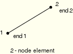
Description: Fluid drag force on the first end of the frame (node 1).
Load ID (*CLOAD/ *DLOAD): FD2
Units: F
Description: Fluid drag force on the second end of the frame (node 2).
Load ID (*CLOAD/ *DLOAD): FDT
Units: FL–1
Description: Tangential fluid drag load.
Load ID (*CLOAD/ *DLOAD): FI
Units: FL–1
Description: Transverse fluid inertia load.
Load ID (*CLOAD/ *DLOAD): FI1
Units: F
Description: Fluid inertia force on the first end of the frame (node 1).
Load ID (*CLOAD/ *DLOAD): FI2
Units: F
Description: Fluid inertia force on the second end of the frame (node 2).
Load ID (*CLOAD/ *DLOAD): PB
Units: FL–1
Description: Buoyancy load (closed-end condition).
Load ID (*CLOAD/ *DLOAD): WDD
Units: FL–1
Description: Transverse wind drag load.
Load ID (*CLOAD/ *DLOAD): WD1
Units: F
Description: Wind drag force on the first end of the frame (node 1).
Load ID (*CLOAD/ *DLOAD): WD2
Units: F
Description: Wind drag force on the second end of the frame (node 2).
Foundations are specified as described in “Element foundations,” Section 2.2.2.
Load ID (*FOUNDATION): FX
Units: FL–2
Description: Stiffness per unit length in global ![]() -direction.
-direction.
Load ID (*FOUNDATION): FY
Units: FL–2
Description: Stiffness per unit length in global ![]() -direction.
-direction.
Load ID (*FOUNDATION): FZ
Units: FL–2
Description: Stiffness per unit length in global ![]() -direction (only for frames in space).
-direction (only for frames in space).
Load ID (*FOUNDATION): F1
Units: FL–2
Description: Stiffness per unit length in frame local ![]() -direction (only for frames in space).
-direction (only for frames in space).
Load ID (*FOUNDATION): F2
Units: FL–2
Description: Stiffness per unit length in frame local ![]() -direction.
-direction.

All element output variables are given at the element ends (nodes 1 and 2) and midpoint (node 3).
SF1 | Axial force. |
SF2 | Transverse shear force in the local 2-direction. |
SF3 | Transverse shear force in the local 1-direction (only available for frames in space). |
SM1 | Bending moment about the local 1-axis. |
SM2 | Bending moment about the local 2-axis (only available for frames in space). |
SM3 | Twisting moment about the frame axis (only available for frames in space). |
See “Frame elements with lumped plasticity,” Section 3.9.2 of the ABAQUS Theory Manual, for a discussion of the section forces and moments.
SEE1 | Elastic axial strain. |
SKE1 | Elastic curvature change about the local 1-axis. |
SKE2 | Elastic curvature change about the local 2-axis (only available for frames in space). |
SKE3 | Elastic twist of the beam (only available for frames in space). |
SEP1 | Plastic axial displacement. |
SKP1 | Plastic rotation about the local 1-axis. |
SKP2 | Plastic rotation about the local 2-axis (only available for frames in space). |
SKP3 | Plastic rotation about the beam axis (only available for frames in space). |
SALPHA1 | Axial force backstress. |
SALPHA2 | Bending moment backstress about the local 1-axis. |
SALPHA3 | Bending moment backstress about the local 2-axis (only available for frames in space). |
SALPHA4 | Twisting moment backstress about the beam axis (only available for frames in space). |


For frames in space an additional node may be given after a frame element's connectivity (in the element definition—see “Element definition,” Section 2.2.1) to define the approximate direction of the first cross-section axis, ![]() . See “Frame elements,” Section 15.4.1, for details.
. See “Frame elements,” Section 15.4.1, for details.