Product: ABAQUS/Standard
The ![]() -integral is widely accepted as a fracture mechanics parameter for both linear and nonlinear material response. It is related to the energy release associated with crack growth and is a measure of the intensity of deformation at a notch or crack tip, especially for nonlinear materials. If the material response is linear, it can be related to the stress intensity factors. Because of the importance of the
-integral is widely accepted as a fracture mechanics parameter for both linear and nonlinear material response. It is related to the energy release associated with crack growth and is a measure of the intensity of deformation at a notch or crack tip, especially for nonlinear materials. If the material response is linear, it can be related to the stress intensity factors. Because of the importance of the ![]() -integral in the assessment of flaws, its accurate numerical evaluation is vital to the practical application of fracture mechanics in design calculations. ABAQUS/Standard provides a procedure for such evaluations of the
-integral in the assessment of flaws, its accurate numerical evaluation is vital to the practical application of fracture mechanics in design calculations. ABAQUS/Standard provides a procedure for such evaluations of the ![]() -integral, based on the virtual crack extension/domain integral methods (Parks, 1977, and Shih, Moran, and Nakamura, 1986). The method is particularly attractive because it is simple to use, adds little to the cost of the analysis, and provides excellent accuracy, even with rather coarse meshes.
-integral, based on the virtual crack extension/domain integral methods (Parks, 1977, and Shih, Moran, and Nakamura, 1986). The method is particularly attractive because it is simple to use, adds little to the cost of the analysis, and provides excellent accuracy, even with rather coarse meshes.
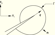
In the context of quasi-static analysis the ![]() -integral is defined in two dimensions as
-integral is defined in two dimensions as
![]()
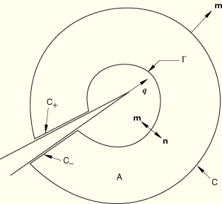
Following Shih et al. (1986), we rewrite Equation 2.16.1–1 in the form
whereUsing the divergence theorem, we convert the closed contour integral into the domain integral
whereIf equilibrium is satisfied and ![]() is a function of the mechanical strain—i.e.,
is a function of the mechanical strain—i.e., ![]() —we have
—we have
![]()
To evaluate these integrals, ABAQUS defines the domain in terms of rings of elements surrounding the crack tip. Different “contours” (domains) are created. The first contour consists of those elements directly connected to crack-tip nodes. The next contour consists of the ring of elements that share nodes with the elements in the the first contour as well as the elements in the first contour. Each subsequent contour is defined by adding the next ring of elements that share nodes with the elements in the previous contour. ![]() is chosen to have a magnitude of zero at the nodes on the outside of the contour and to be one (in the crack direction) at all nodes inside the contour except for the midside nodes (if they exist) in the outer ring of elements. These midside nodes are assigned a value between zero and one according to the position of the node on the side of the element.
is chosen to have a magnitude of zero at the nodes on the outside of the contour and to be one (in the crack direction) at all nodes inside the contour except for the midside nodes (if they exist) in the outer ring of elements. These midside nodes are assigned a value between zero and one according to the position of the node on the side of the element.
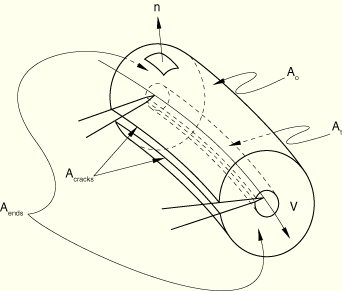
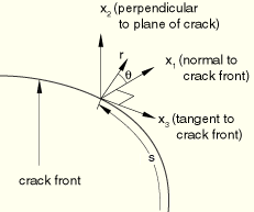
The ![]() -integral can be extended to three dimensions by considering a crack with a tangentially continuous front, as shown in Figure 2.16.1–3. The local direction of virtual crack extension is again given by
-integral can be extended to three dimensions by considering a crack with a tangentially continuous front, as shown in Figure 2.16.1–3. The local direction of virtual crack extension is again given by ![]() ,
,
Figure 2.16.1–3 Definition of local orthogonal Cartesian coordinates at the point ![]() on the crack front; the crack is in the
on the crack front; the crack is in the ![]() –
–![]() plane.
plane.
For a virtual crack advance ![]() in the plane of a three-dimensional crack, the energy release rate is given by
in the plane of a three-dimensional crack, the energy release rate is given by
Using the divergence theorem, we obtain
To obtain ![]() at each node set
at each node set ![]() along the crack front line,
along the crack front line, ![]() is discretized with the same interpolation functions as those used in the finite elements along the crack front:
is discretized with the same interpolation functions as those used in the finite elements along the crack front:
![]()