This option is used to define nodes by accepting coordinates relative to a specified local rectangular coordinate system and generating the nodal coordinates in the global coordinate system.
Products: ABAQUS/Standard ABAQUS/Explicit
Type: Model data
Level: Part Part Instance
First line:
![]() , global
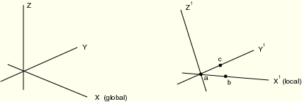
, global ![]() -coordinate of the origin of the local coordinate system (point
-coordinate of the origin of the local coordinate system (point ![]() in Figure 18.56–1).
in Figure 18.56–1).
![]() , global
, global ![]() -coordinate of the origin of the local coordinate system.
-coordinate of the origin of the local coordinate system.
![]() , global
, global ![]() -coordinate of the origin of the local coordinate system.
-coordinate of the origin of the local coordinate system.
The following entries are not needed for a pure translation:
![]() , global
, global ![]() -coordinate of a point on the
-coordinate of a point on the ![]() -axis of the local coordinate system (point
-axis of the local coordinate system (point ![]() in Figure 18.56–1).
in Figure 18.56–1).
![]() , global
, global ![]() -coordinate of a point on the
-coordinate of a point on the ![]() -axis of the local coordinate system.
-axis of the local coordinate system.
![]() , global
, global ![]() -coordinate of a point on the
-coordinate of a point on the ![]() -axis of the local coordinate system.
-axis of the local coordinate system.
Second line (optional; if not provided, the ![]() -axis direction remains unchanged, and the
-axis direction remains unchanged, and the ![]() -axis is projected onto the
-axis is projected onto the ![]() plane):
plane):
![]() , global
, global ![]() -coordinate of a point in the
-coordinate of a point in the ![]() plane of the local coordinate system, on the side of the positive
plane of the local coordinate system, on the side of the positive ![]() -axis (for example, point
-axis (for example, point ![]() in Figure 18.56–1).
in Figure 18.56–1).
![]() , global
, global ![]() -coordinate of a point in the
-coordinate of a point in the ![]() plane of the local coordinate system, on the side of the positive
plane of the local coordinate system, on the side of the positive ![]() -axis.
-axis.
![]() , global
, global ![]() -coordinate of a point in the
-coordinate of a point in the ![]() plane of the local coordinate system, on the side of the positive
plane of the local coordinate system, on the side of the positive ![]() -axis.
-axis.