This option is used to define a local coordinate system for definition of material properties; for material calculations at integration points; for element property definitions (e.g., connector elements); for output of components of stress, strain, and element section forces; and for kinematic and distributing coupling constraints. In ABAQUS/Standard it can be used to define local directions for contact pair interaction properties and spring, dashpot, and JOINTC elements; for definition of local free directions for inertia relief loads; and for output of components of surface variables.
Products: ABAQUS/Standard ABAQUS/Explicit
Type: Model data
Level: Part Part Instance Assembly
Set this parameter equal to the name to be used to identify the orientation definition. Orientation names in the same input file must be unique.
Set DEFINITION=COORDINATES (default) to define the local system by giving the coordinates of the three points ![]() ,
, ![]() , and, optionally,
, and, optionally, ![]() (the origin) appropriate to the SYSTEM choice from Figure 15.1–1.
(the origin) appropriate to the SYSTEM choice from Figure 15.1–1.
Set DEFINITION=NODES to define the local system by giving global node numbers for points ![]() ,
, ![]() , and, optionally,
, and, optionally, ![]() (the origin).
(the origin).
Set DEFINITION=OFFSET TO NODES to define the local system by giving local node numbers (on the element where the orientation is being used) to define the points ![]() ,
, ![]() , and, optionally,
, and, optionally, ![]() (the origin) in Figure 15.1–1. This parameter value cannot be used with spring, dashpot, or JOINTC elements. In addition, it cannot be used with the *KINEMATIC COUPLING, *INERTIA RELIEF, or *CONTACT PAIR options.
(the origin) in Figure 15.1–1. This parameter value cannot be used with spring, dashpot, or JOINTC elements. In addition, it cannot be used with the *KINEMATIC COUPLING, *INERTIA RELIEF, or *CONTACT PAIR options.
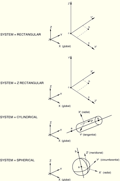
Set SYSTEM=RECTANGULAR (default) to define a rectangular Cartesian system by the three points ![]() ,
, ![]() , and
, and ![]() shown in Figure 15.1–1. Point
shown in Figure 15.1–1. Point ![]() is the origin of the system, point
is the origin of the system, point ![]() must lie on the
must lie on the ![]() -axis, and point
-axis, and point ![]() must lie on the
must lie on the ![]() -
-![]() plane. Although not necessary, it is intuitive to select point
plane. Although not necessary, it is intuitive to select point ![]() such that it is on or near the local
such that it is on or near the local ![]() -axis.
-axis.
Set SYSTEM=CYLINDRICAL to define a cylindrical system by giving the two points ![]() and
and ![]() on the polar axis of the cylindrical system (Figure 15.1–1). The local axes are 1=radial, 2=circumferential, 3=axial.
on the polar axis of the cylindrical system (Figure 15.1–1). The local axes are 1=radial, 2=circumferential, 3=axial.
Set SYSTEM=SPHERICAL to define a spherical system by giving the center of the sphere, ![]() , and point
, and point ![]() on the polar axis (Figure 15.1–1). The local axes are 1=radial, 2=circumferential, 3=meridional.
on the polar axis (Figure 15.1–1). The local axes are 1=radial, 2=circumferential, 3=meridional.
Set SYSTEM=Z RECTANGULAR in an ABAQUS/Standard analysis to define a rectangular Cartesian system by the three points ![]() ,
, ![]() , and
, and ![]() shown in Figure 15.1–1. Point
shown in Figure 15.1–1. Point ![]() is the origin of the system, point
is the origin of the system, point ![]() must lie on the
must lie on the ![]() -axis, and point
-axis, and point ![]() must lie on the
must lie on the ![]() -
-![]() plane. Although not necessary, it is intuitive to select point
plane. Although not necessary, it is intuitive to select point ![]() such that it is on or near the local
such that it is on or near the local ![]() -axis.
-axis.
Set SYSTEM=USER in an ABAQUS/Standard analysis to define the local coordinate system in user subroutine ORIENT. The DEFINITION parameter and any data lines associated with the option are ignored if SYSTEM=USER.
First line:
![]() -coordinate of point
-coordinate of point ![]() .
.
![]() -coordinate of point
-coordinate of point ![]() .
.
![]() -coordinate of point
-coordinate of point ![]() .
.
![]() -coordinate of point
-coordinate of point ![]() .
.
![]() -coordinate of point
-coordinate of point ![]() .
.
![]() -coordinate of point
-coordinate of point ![]() .
.
The following items, the coordinates of point ![]() (the origin), are optional and relevant only for SYSTEM=RECTANGULAR and SYSTEM=Z RECTANGULAR. The default location of the origin,
(the origin), are optional and relevant only for SYSTEM=RECTANGULAR and SYSTEM=Z RECTANGULAR. The default location of the origin, ![]() , is the global origin.
, is the global origin.
![]() -coordinate of point
-coordinate of point ![]() .
.
![]() -coordinate of point
-coordinate of point ![]() .
.
![]() -coordinate of point
-coordinate of point ![]() .
.
Second line (mandatory for shells, membranes, gaskets, composite solid sections, and contact pairs):
Local direction about which the additional rotation ![]() is given. The default is the local 1-direction. For shell and membrane elements this direction should have a nonzero component in the direction of the normal to the surface.
is given. The default is the local 1-direction. For shell and membrane elements this direction should have a nonzero component in the direction of the normal to the surface.
Additional rotation ![]() , in degrees. The default is zero degrees.
, in degrees. The default is zero degrees.
First line:
Node number of the node at point ![]() .
.
Node number of the node at point ![]() .
.
The next item, specification of point ![]() (the origin), is optional and relevant only for SYSTEM=RECTANGULAR and SYSTEM=Z RECTANGULAR. The default location of the origin,
(the origin), is optional and relevant only for SYSTEM=RECTANGULAR and SYSTEM=Z RECTANGULAR. The default location of the origin, ![]() , is the global origin.
, is the global origin.
Node number of the node at point ![]() .
.
Second line (mandatory for shells, membranes, gaskets, composite solid sections, and contact pairs):
Local direction about which the additional rotation ![]() is given. The default is the local 1-direction. For shell and membrane elements this direction should have a nonzero component in the direction of the normal to the surface.
is given. The default is the local 1-direction. For shell and membrane elements this direction should have a nonzero component in the direction of the normal to the surface.
Additional rotation ![]() , in degrees. The default is zero degrees.
, in degrees. The default is zero degrees.
First line:
Local node number of point ![]() .
.
Local node number of point ![]() .
.
The next item, specification of point ![]() (the origin), is optional and relevant only for SYSTEM=RECTANGULAR and SYSTEM=Z RECTANGULAR. The default location of the origin,
(the origin), is optional and relevant only for SYSTEM=RECTANGULAR and SYSTEM=Z RECTANGULAR. The default location of the origin, ![]() , is the first node of the element (local node number 1).
, is the first node of the element (local node number 1).
Local node number of point ![]() .
.
Second line (mandatory for shells, membranes, gaskets, and composite solid sections):
Local direction about which the additional rotation ![]() is given. The default direction for additional rotation is the local 1-direction. For shell and membrane elements this direction should have a nonzero component in the direction of the normal to the surface.
is given. The default direction for additional rotation is the local 1-direction. For shell and membrane elements this direction should have a nonzero component in the direction of the normal to the surface.
Additional rotation ![]() , in degrees. The default is zero degrees.
, in degrees. The default is zero degrees.
No data lines are used with this option when SYSTEM=USER is specified. Instead, user subroutine ORIENT must be used to define the orientation (“ORIENT,” Section 25.2.14 of the ABAQUS Analysis User's Manual).