This option is used to map a set of nodes from one coordinate system to another.
Products: ABAQUS/Standard ABAQUS/Explicit
Type: Model data
Level: This option is not supported in a model defined in terms of an assembly of part instances.
Set this parameter equal to the name of the node set containing the nodes to be mapped. The nodes that are mapped are those that belong to this set at the time this option is encountered.
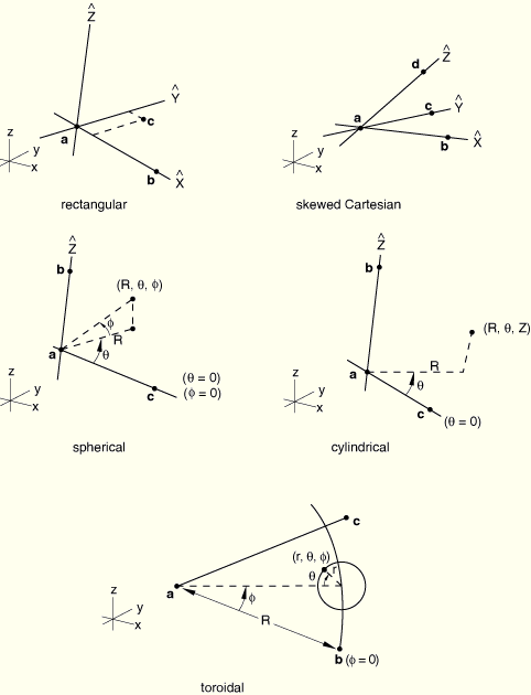
Set TYPE=RECTANGULAR to introduce a simple shift or rotation. Point ![]() in Figure 14.4–1 defines the origin of the local rectangular coordinate system defining the map. The local
in Figure 14.4–1 defines the origin of the local rectangular coordinate system defining the map. The local ![]() -axis is defined by the line joining points
-axis is defined by the line joining points ![]() and
and ![]() . The local
. The local ![]() –
–![]() plane is defined by the plane passing through points
plane is defined by the plane passing through points ![]() ,
, ![]() , and
, and ![]() .
.
Set TYPE=CYLINDRICAL to map from cylindrical coordinates. Point ![]() in Figure 14.4–1 defines the origin of the local cylindrical coordinate system defining the map. The line going through point
in Figure 14.4–1 defines the origin of the local cylindrical coordinate system defining the map. The line going through point ![]() and point
and point ![]() defines the
defines the ![]() -axis of the local cylindrical coordinate system. The local
-axis of the local cylindrical coordinate system. The local ![]() –
–![]() plane for
plane for ![]() is defined by the plane passing through points
is defined by the plane passing through points ![]() ,
, ![]() , and
, and ![]() .
.
Set TYPE=DIAMOND to map from skewed Cartesian coordinates. Point ![]() in Figure 14.4–1 defines the origin of the local diamond coordinate system defining the map. The line going through point
in Figure 14.4–1 defines the origin of the local diamond coordinate system defining the map. The line going through point ![]() and point
and point ![]() defines the
defines the ![]() -axis of the local coordinate system. The line going through point
-axis of the local coordinate system. The line going through point ![]() and point
and point ![]() defines the
defines the ![]() -axis of the local coordinate system. The line going through point
-axis of the local coordinate system. The line going through point ![]() and point
and point ![]() defines the
defines the ![]() -axis of the local coordinate system.
-axis of the local coordinate system.
Set TYPE=SPHERICAL to map from spherical coordinates. Point ![]() in Figure 14.4–1 defines the origin of the local spherical coordinate system defining the map. The line going through point
in Figure 14.4–1 defines the origin of the local spherical coordinate system defining the map. The line going through point ![]() and point
and point ![]() defines the polar axis of the local spherical coordinate system. The plane passing through point
defines the polar axis of the local spherical coordinate system. The plane passing through point ![]() and perpendicular to the polar axis defines the
and perpendicular to the polar axis defines the ![]() plane. The plane passing through points
plane. The plane passing through points ![]() ,
, ![]() , and
, and ![]() defines the local
defines the local ![]() plane.
plane.
Set TYPE=TOROIDAL to map from toroidal coordinates. Point ![]() in Figure 14.4–1 defines the origin of the local toroidal coordinate system defining the map. The axis of the local toroidal system lies in the plane defined by points
in Figure 14.4–1 defines the origin of the local toroidal coordinate system defining the map. The axis of the local toroidal system lies in the plane defined by points ![]() ,
, ![]() , and
, and ![]() . The
. The ![]() -coordinate of the toroidal system is defined by the distance between points
-coordinate of the toroidal system is defined by the distance between points ![]() and
and ![]() . The line between points
. The line between points ![]() and
and ![]() defines the
defines the ![]() position. For every value of
position. For every value of ![]() the
the ![]() -coordinate is defined in a plane perpendicular to the plane defined by the points
-coordinate is defined in a plane perpendicular to the plane defined by the points ![]() ,
, ![]() , and
, and ![]() and perpendicular to the axis of the toroidal system.
and perpendicular to the axis of the toroidal system. ![]() lies in the plane defined by the points by
lies in the plane defined by the points by ![]() ,
, ![]() , and
, and ![]() .
.
Set TYPE=BLENDED to map via blended quadratics in an ABAQUS/Standard analysis.
First line:
![]() -coordinate of point
-coordinate of point ![]() (see Figure 14.4–1).
(see Figure 14.4–1).
![]() -coordinate of point
-coordinate of point ![]() .
.
![]() -coordinate of point
-coordinate of point ![]() .
.
![]() -coordinate of point
-coordinate of point ![]() .
.
![]() -coordinate of point
-coordinate of point ![]() .
.
![]() -coordinate of point
-coordinate of point ![]() .
.
Second line:
![]() -coordinate of point
-coordinate of point ![]() .
.
![]() -coordinate of point
-coordinate of point ![]() .
.
![]() -coordinate of point
-coordinate of point ![]() .
.
The following fields are needed only for TYPE=DIAMOND:
![]() -coordinate of point
-coordinate of point ![]() .
.
![]() -coordinate of point
-coordinate of point ![]() .
.
![]() -coordinate of point
-coordinate of point ![]() .
.
If TYPE=RECTANGULAR is specified and only point ![]() is given, the coordinates of the nodes in the set are simply shifted by
is given, the coordinates of the nodes in the set are simply shifted by ![]() ,
, ![]() , and
, and ![]() .
.
Third line:
Scale factor to be applied to the first local coordinate before mapping. If the value entered is zero or blank, a scale factor of 1.0 is assumed.
Scale factor to be applied to the second local coordinate before mapping. If the value entered is zero or blank, a scale factor of 1.0 is assumed.
Scale factor to be applied to the third local coordinate before mapping. If the value entered is zero or blank, a scale factor of 1.0 is assumed.
First line:
Node number of the first control node.
![]() -coordinate of the point to which this control node is to be mapped.
-coordinate of the point to which this control node is to be mapped.
![]() -coordinate of the point to which this control node is to be mapped.
-coordinate of the point to which this control node is to be mapped.
![]() -coordinate of the point to which this control node is to be mapped.
-coordinate of the point to which this control node is to be mapped.
Second line:
Node number of the second control node.
![]() -coordinate of the point to which this control node is to be mapped.
-coordinate of the point to which this control node is to be mapped.
![]() -coordinate of the point to which this control node is to be mapped.
-coordinate of the point to which this control node is to be mapped.
![]() -coordinate of the point to which this control node is to be mapped.
-coordinate of the point to which this control node is to be mapped.
Continue, giving up to 20 control nodes, but giving at least the eight corner nodes. If an edge of the blended mapping is to be mapped linearly, the corresponding mid-edge control node can be omitted from the list. This is done by inserting a line with node number 0 only (a blank line) in place of the definition of the control node and its mapped coordinates. The control nodes do not have to be nodes in the finite element model—they can be nodes used just for mesh generation. ABAQUS eliminates any nodes that are not used in the analysis model before doing the analysis.