Meshing the assembly is divided into the following operations:
Making sure the part instances can be meshed and creating additional partitions where necessary.
Assigning mesh attributes to the part instances.
Seeding the part instances.
Meshing the part instances.
When you enter the Mesh module, ABAQUS/CAE color codes regions of the model according to the methods it will use to generate a mesh:
Green indicates that a region can be meshed using structured methods.
Yellow indicates that a region can be meshed using sweep methods.
Orange indicates that a region cannot be meshed using the default element shape assignment (hexahedral) and must be partitioned further. (Alternatively, you can mesh any model by assigning tetrahedral elements to the model and using the free meshing technique.)
For the tutorial ABAQUS/CAE indicates that the hinges need to be partitioned to be meshed using hexahedral-shaped elements. Specifically, areas surrounding the hole in the flange and the lubrication hole must be partitioned. The partitioned hinges are shown in Figure C–47.
Use the following techniques to help you select faces and vertices during the partitioning process:
Use a combination of the view manipulation tools, the display option tools in the toolbar, and the tools in the Views toolbox to resize and reposition the model as necessary. (The Views toolbox appears when you select ![]() from the main menu bar.)
from the main menu bar.)
From the prompt area, click the selection options tool ![]() and toggle off the closest object tool
and toggle off the closest object tool ![]() to cycle through the possible selections using the Next and Previous buttons in the prompt area.
to cycle through the possible selections using the Next and Previous buttons in the prompt area.
You will probably find the magnification tool ![]() and the rotation tool
and the rotation tool ![]() especially useful.
especially useful.
When necessary, click the Iso tool in the Views toolbox to return the model to its original size and position in the viewport.
Recall that part instances are classified as dependent by default. All dependent instances of a part must possess identical geometry (including partitions) and meshes. To satisfy this requirement, all partitions must be created in the original part and all mesh attributes must be assigned to the original part. You will need to examine the parts individually to determine what action (if any) needs to be taken to create a mesh using hexahedral elements.
Note: The advantage of dependent part instances is that if you create multiple instances of the same part, you need only manipulate and mesh the original part; these features are automatically inherited by the dependent instances. Since you created only one instance of each part in this tutorial, you could have created independent part instances and worked with them just as easily. This would have allowed you to create partitions and assign mesh attributes at the assembly level rather than at the part level. You can make a dependent part instance independent by clicking mouse button 3 on its name underneath the Instances container in the Model Tree and selecting Make independent. In what follows, we assume the part instances remain dependent.
To decide what needs to be partitioned:
In the Model Tree, expand Hinge-hole underneath the Parts container and double-click Mesh in the list that appears.
Note: If the part instance were independent, you would instead expand the instance name underneath the Instances container and click Mesh in the list that would appear.
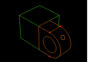
ABAQUS/CAE displays the hinge piece in orange, which indicates that it needs to be partitioned to be meshed using hexahedral elements, as shown in Figure C–48.
Use the Object field that appears in the context bar to display the solid hinge in the viewport. This part is also colored orange, indicating that it too needs to be partitioned to mesh it with hexahedral elements.
Select the pin from the Object field in the context bar. ABAQUS/CAE displays the pin in orange because it is an analytical rigid surface and cannot be meshed.
Thus, both hinge pieces need to be partitioned to mesh them with hexahedral elements; the pin requires no further action. Begin by partitioning the solid hinge piece.
Select the solid hinge piece from the Object field in the context bar to display it in the viewport. From the main menu bar, select Tools![]() Partition to partition the solid hinge.
Partition to partition the solid hinge.
ABAQUS/CAE displays the Create Partition dialog box.
From the Create Partition dialog box, choose the Cell partition type. Select the Extend face method, and click Apply.
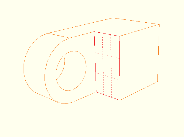
Select the face to extend, as shown by the gridded face in Figure C–49. If necessary, toggle off the closest object tool ![]() to make the desired face selectable.
to make the desired face selectable.
From the prompt area, click Create Partition.
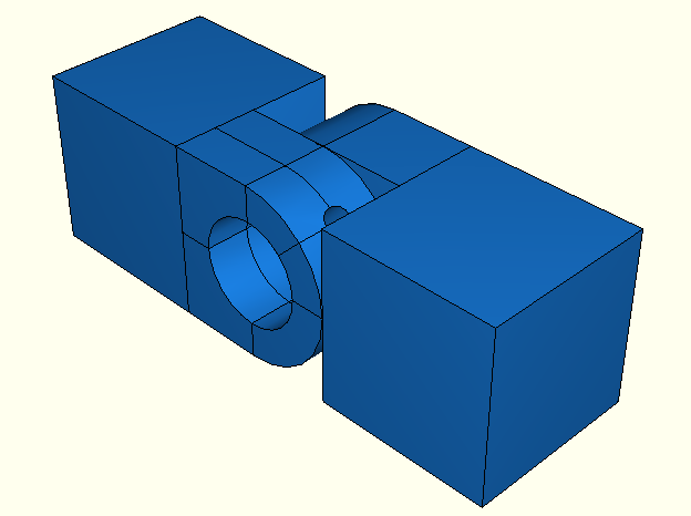
ABAQUS/CAE creates the partition, as shown in Figure C–50.
Tip:
If the partition is not located correctly, select Feature![]() Delete from the main menu bar and select the partition to delete.
Delete from the main menu bar and select the partition to delete.
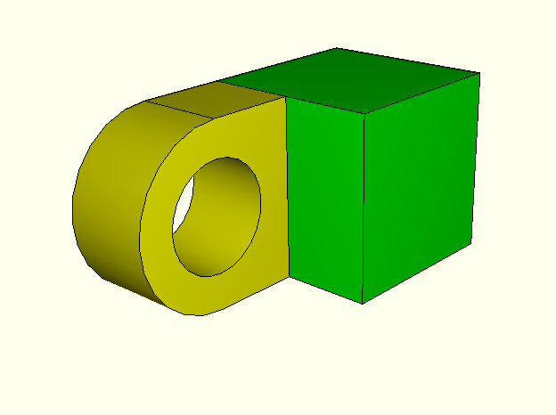
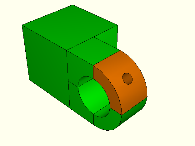
ABAQUS/CAE colors the cube portion of the solid hinge piece green to indicate that it can be meshed using the structured meshing technique; it colors the flange of the solid hinge piece yellow to indicate that it can be meshed using a swept mesh.
Make the hinge piece with the lubrication hole current in the viewport by selecting it from the Object field that appears in the context bar. Use a similar method to that described in the previous steps to create a partition between the cube and the flange of this piece.
Again the cube turns green to indicate that it can be meshed using structured meshing, but the flange containing the lubrication hole remains orange, indicating that you need to perform additional partitioning to mesh this flange.
For ABAQUS/CAE to mesh the flange with the lubrication hole, it must be partitioned into the regions shown in Figure C–51.
To partition the flanges:
From the Create Partition dialog box, select the Define cutting plane method, and click Apply.
Select the flange of the hinge with the lubrication hole. Click Done to indicate you have finished selecting cells.
ABAQUS/CAE provides three methods for specifying the cutting plane:
Select a point and a normal. The cutting plane passes through the selected point, normal to the selected edge.
Select three non-colinear points. The cutting plane passes through each point.
Select an edge and a point along the edge. The cutting plane passes through the selected point, normal to the selected edge.
From the buttons in the prompt area, select 3 points.
ABAQUS/CAE highlights points that you can select.
Select three points that cut the flanges in half with a vertical partition, as shown in Figure C–52.
Tip: You may find it easier to select the desired points if you magnify, rotate, and pan the model to obtain a more convenient view.
From the prompt area, click Create Partition.
ABAQUS/CAE creates the desired partitions.
Partition the flange of the solid hinge piece using a similar procedure.
You have now partitioned each of the flanges into two regions; you need to create additional partitions that cut these regions in half horizontally, as shown in Figure C–53 for the hinge piece with the lubrication hole.
Use the Define cutting plane method to create the desired partitions on each hinge piece. Remember that since the cutting plane extends infinitely, points that define it need not be on the cells being partitioned; for example, you can select midpoints of edges around the cube to define the cutting plane through the flange regions of a given part. The plane extends infinitely and partitions the selected regions anywhere an intersection occurs.Partition the flanges of both hinge pieces in half horizontally. Once this is complete, the solid hinge piece is colored green; for the hinge piece containing the lubrication hole, ABAQUS/CAE colors the region with the hole orange to indicate that it still cannot be meshed. Use the Define cutting plane method to partition the four regions in this flange, as shown in Figure C–54.
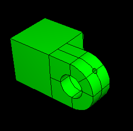
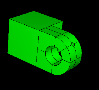
The coloring of the part indicates that it can now be meshed completely; thus, no additional partitions are required.
From the prompt area, click Done to indicate that you have finished partitioning cells.
From the Create Partition dialog box, click Cancel.
The partitioning operations are now complete. Select Assembly in the Object field of the context bar to display the model assembly in the viewport. The model assembly with all the partitions is shown in Figure C–55.
In this section you will use the Mesh Controls dialog box to examine the techniques that ABAQUS/CAE will use to mesh the parts and the shape of the elements that ABAQUS/CAE will generate.
To assign the mesh controls:
You cannot mesh an analytical rigid surface. As a result you cannot apply mesh controls to an analytical rigid surface; neither can you seed it or assign an element type to it. Thus, you need only concern yourself with the hinge pieces. Since the instances are dependent on the original part definition, you must assign mesh attributes (controls, type, and seed size) to each hinge piece individually. For convenience, you will begin with the hinge piece with the lubrication hole.
Make the hinge piece with the hole current in the viewport. From the main menu bar, select Mesh![]() Controls.
Controls.
Drag a square around the part to select all regions of the part, and click Done to indicate your selection is complete.
The hinge piece appears red in the viewport to indicate that you have selected it, and ABAQUS/CAE displays the Mesh Controls dialog box.
In the dialog box, accept Hex as the default Element Shape selection.
Accept Structured as the meshing technique that ABAQUS/CAE will apply.
Click OK to assign the mesh controls and to close the dialog box.
Click Done in the prompt area.
Repeat the above steps for the solid hinge piece.
In this section you will use the Element Type dialog box to examine the element types that are assigned to each part. For convenience, you will begin with the hinge piece with the lubrication hole.
To assign an ABAQUS element type:
Make the hinge piece with the hole current in the viewport. From the main menu bar, select Mesh![]() Element Type.
Element Type.
Select the hinge piece using the same technique described in the mesh controls procedure, and click Done to indicate your selection is complete.
ABAQUS/CAE displays the Element Type dialog box.
In the dialog box, accept Standard as the Element Library selection.
Accept Linear as the Geometric Order selection.
Accept 3D Stress as the default Family of elements.
Click the Hex tab, and select Reduced Integration as the Element Controls method if it is not already selected.
A description of the default element type, C3D8R, appears at the bottom of the dialog box. ABAQUS/CAE will now associate C3D8R elements with the elements in the mesh.
Click OK to assign the element type and to close the dialog box.
Click Done in the prompt area.
Repeat the above steps for the solid hinge piece.
The next step of the meshing process is to seed each of the part instances. Seeds represent the approximate locations of nodes and indicate the target density of the mesh you would like to generate. You can select seeding based on the number of elements to generate along an edge or on the average element size, or you can bias seed distribution toward one end of an edge. For the tutorial you will seed the parts so that the hinge pieces have an average element size of 0.004. For convenience, you will begin with the hinge piece with the lubrication hole.
To seed the parts:
Make the hinge piece with the hole current in the viewport. From the main menu bar, select Seed![]() Part.
Part.
Select the hinge piece with the lubrication hole using the same technique described in the mesh controls procedure, and click Done to indicate your selection is complete.
In the Global Seeds dialog box that appears, enter an approximate global element size of 0.004, and click OK.
Seeds appear on all the edges.
Click Done in the prompt area.
Repeat the above steps for the solid hinge piece.
You are now ready to mesh the parts.
In this section you will mesh the parts. For convenience, you will begin with the hinge piece with the lubrication hole.
To mesh the assembly:
Make the hinge piece with the hole current in the viewport. From the main menu bar, select Mesh![]() Part.
Part.
Click Yes in the prompt area to create the mesh.
ABAQUS/CAE meshes the part.
Repeat the above steps for the solid hinge piece.
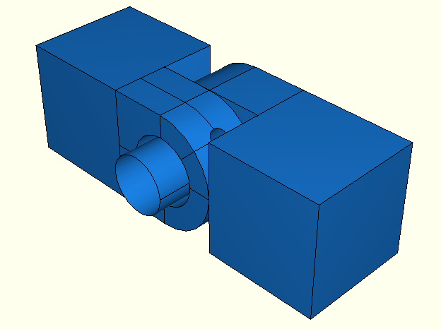
The meshing operations are now complete. Display the model assembly in the viewport to see the final mesh, as illustrated in Figure C–56.