Products: ABAQUS/Standard ABAQUS/Explicit
This analysis illustrates how extrusion problems can be simulated with ABAQUS. In this particular problem the radius of an aluminum cylindrical bar is reduced 33% by an extrusion process. The generation of heat due to plastic dissipation inside the bar and the frictional heat generation at the workpiece/die interface are considered.

The bar has an initial radius of 100 mm and is 300 mm long. Figure 1.3.5–1 shows half of the cross-section of the bar, modeled with first-order axisymmetric elements (CAX4T and CAX4RT elements in ABAQUS/Standard and CAX4RT elements in ABAQUS/Explicit).
The die is assumed to be rigid. In ABAQUS/Standard the die is modeled with CAX4T elements, which are made into an isothermal rigid body with the *RIGID BODY, ISOTHERMAL option. The *SURFACE option is used to define the slave surface on the outside of the bar and the master surface on the inside of the die. To model a die that has no sharp corners and is smooth in the transition region, the SMOOTH parameter on the *CONTACT PAIR option is set to 0.48.
In ABAQUS/Explicit the die is modeled with either an analytical rigid surface or discrete rigid elements (RAX2). The analytical rigid surface is defined using the *RIGID BODY option in conjunction with the *SURFACE option. The FILLET RADIUS parameter on the *SURFACE option is set to 0.075 to remove sharp corners in the transition region of the die.
For simplicity we do not model any heat transfer in the die—we simply fix the temperature of the rigid body reference node and assume that no heat is transmitted between the bar and the die. Half the heat dissipated as a result of friction is assumed to be conducted into the workpiece; the other half is conducted into the die. 90% of the nonrecoverable work because of plasticity is assumed to heat the work material. More realistic analysis would include thermal modeling of the die.
The ABAQUS/Explicit simulations are also performed with adaptive meshing and ENHANCED hourglass control.

The material model is chosen to reflect the response of a typical commercial purity aluminum alloy. The material is assumed to harden isotropically. The dependence of the flow stress on the temperature is included, but strain rate dependence is ignored. Instead, representative material data at a strain rate of 0.1 sec–1 are selected to characterize the flow strength.
The interface is assumed to have no conductive properties. Coulomb friction is assumed for the mechanical behavior, with a friction coefficient of 0.1. The *GAP HEAT GENERATION option is used to specify the fraction, ![]() , of total heat generated by frictional dissipation that is transferred to the two bodies in contact. Half of this heat is conducted into the workpiece, and the other half is conducted into the die.
, of total heat generated by frictional dissipation that is transferred to the two bodies in contact. Half of this heat is conducted into the workpiece, and the other half is conducted into the die.

In the first step the bar is moved to a position where contact is established and slipping of the workpiece against the die begins. In the second step the bar is extruded through the die to realize the extrusion process. This is accomplished by prescribing displacements to the nodes at the top of the bar. In the third step the contact elements are removed in preparation for the cool down portion of the simulation. In ABAQUS/Standard this is performed in a single step: the bar is allowed to cool down using film conditions, and deformation is driven by thermal contraction during the fourth step. In ABAQUS/Explicit the cool down simulation is broken into two steps: the first introduces viscous pressure to damp out dynamic effects and, thus, allow the bar to reach static equilibrium quickly; the balance of the cool down simulation is performed in a fifth step. The relief of residual stresses through creep is not analyzed in this example.
In ABAQUS/Explicit mass scaling is used to reduce the computational cost of the analysis; nondefault hourglass control is used to control the hourglassing in the model. The default integral viscoelastic approach to hourglass control generally works best for problems where sudden dynamic loading occurs; a stiffness-based hourglass control is recommended for problems where the response is quasi-static. A combination of stiffness and viscous hourglass control is used in this problem.
For purposes of comparison a second problem is also analyzed, in which the first two steps of the previous analysis are repeated in a static analysis with the adiabatic heat generation capability. The adiabatic analysis neglects heat conduction in the bar. Frictional heat generation must also be ignored in this case. This problem is analyzed only in ABAQUS/Standard.
The following discussion centers around the results obtained with ABAQUS/Standard. The results of the ABAQUS/Explicit simulation are in close agreement with those obtained with ABAQUS/Standard.
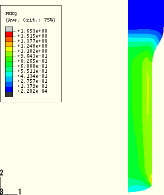
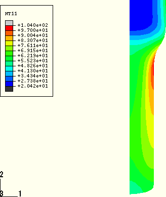
Figure 1.3.5–2 shows the deformed configuration after Step 2 of the analysis. Figure 1.3.5–3 and Figure 1.3.5–4 show contour plots of plastic strain and temperature at the end of Step 2 for the fully coupled analysis. The plastic deformation is most severe near the surface of the workpiece, where plastic strains exceed 100%. The peak temperature also occurs at the surface of the workpiece because of plastic deformation and frictional heating. The peak temperature occurs immediately after the radial reduction zone of the die. This is expected for two reasons. First, the material that is heated by dissipative processes in the reduction zone will cool by conduction as the material progresses through the postreduction zone. Second, frictional heating is largest in the reduction zone because of the larger values of shear stress in that zone. The peak surface temperature is approximately 106°C (i.e., ![]() 86°C).
86°C).
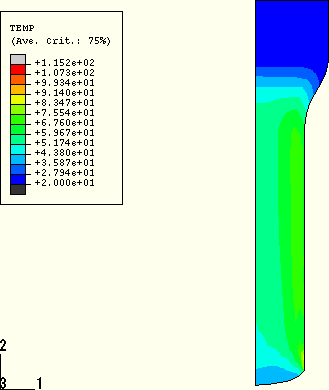
If we ignore the zone of extreme distortion at the end of the bar, the temperature increase on the surface is not as large for the adiabatic analysis (Figure 1.3.5–5) because of the absence of frictional heating. The surface temperatures in this analysis are approximately 80°C. As expected, the temperature field contours for the adiabatic heating analysis, Figure 1.3.5–5, are very similar to the contours of plastic strain, Figure 1.3.5–3, from the thermally coupled analysis.
As noted earlier, excellent agreement is observed for the results obtained with ABAQUS/Explicit (using both default and ENHANCED hourglass control) and ABAQUS/Standard. Figure 1.3.5–6 compares the effects of adaptive meshing on the element quality. The results obtained with adaptive meshing show significantly reduced mesh distortion. The material point in the bar that experiences the largest temperature rise during the course of the simulation is indicated (node 2029 in the model without adaptivity). Figure 1.3.5–7 compares the results obtained with ABAQUS/Explicit for the temperature history of this material point against the same results obtained with ABAQUS/Standard.
Thermally coupled extrusion using CAX4T elements with frictional heat generation.
Thermally coupled extrusion using CAX4RT elements with frictional heat generation.
Extrusion with adiabatic heat generation and without frictional heat generation.
Thermally coupled extrusion with frictional heat generation and automatic stabilization.
Thermally coupled extrusion with frictional heat generation and without adaptive meshing; die modeled with an analytical rigid surface; kinematic mechanical contact.
Thermally coupled extrusion with frictional heat generation and without adaptive meshing; die modeled with an analytical rigid surface; kinematic mechanical contact; enhanced hourglass control.
Thermally coupled extrusion with frictional heat generation and adaptive meshing; die modeled with an analytical rigid surface; kinematic mechanical contact.
Thermally coupled extrusion with frictional heat generation and adaptive meshing; die modeled with an analytical rigid surface; kinematic mechanical contact; enhanced hourglass control.
Thermally coupled extrusion with frictional heat generation and without adaptive meshing; die modeled with RAX2 elements; kinematic mechanical contact.
Thermally coupled extrusion with frictional heat generation and without adaptive meshing; die modeled with RAX2 elements; kinematic mechanical contact; enhanced hourglass control.
Thermally coupled extrusion with frictional heat generation and without adaptive meshing; die modeled with an analytical rigid surface; penalty mechanical contact.
Thermally coupled extrusion with frictional heat generation and without adaptive meshing; die modeled with an analytical rigid surface; penalty mechanical contact; enhanced hourglass control.

Figure 1.3.5–3 Plastic strain contours, Step 2, thermally coupled analysis (frictional heat generation), ABAQUS/Standard.

Figure 1.3.5–4 Temperature contours, Step 2, thermally coupled analysis (frictional heat generation), ABAQUS/Standard.

Figure 1.3.5–5 Temperature contours, Step 2, adiabatic heat generation (without heat generation due to friction), ABAQUS/Standard.
