Products: ABAQUS/Standard ABAQUS/Explicit
This example is intended to illustrate and verify the use of the tie constraint (*TIE) in a simple acoustic system, using several procedures.
The problem considers steady-state and transient wave propagation in a rectangular duct. Figure 1.10.5–1 shows the two-dimensional test mesh. There are two unconnected regions: the lower region has the tie constraints, and the simpler upper region is used for comparison.
The lower region is made up of five subregions, totaling 5000 mm long by 1000 mm wide. In ABAQUS/Standard the first (leftmost) subregion consists of AC2D6 elements, the second of AC2D3 elements, the third of AC2D4 elements, the fourth (far right, upper) of AC2D4 elements, and the last of AC2D8 elements. The nodes on the intersecting surfaces do not coincide. The upper reference domain is 5000 mm long by 80 mm wide and consists of AC2D4 elements. In ABAQUS/Explicit the AC2D4 and AC2D8 elements defined above are replaced by AC2D4R elements, and the AC2D6 elements are replaced with AC2D3 elements. Both domains are made of an acoustic material with a bulk modulus of 0.142 MPa and a density of 1.21 kg per cubic meter. The subregions of the lower domain are connected with *TIE constraints. In each *TIE constraint pair the more refined surface is defined as the slave.

For the *STEADY STATE DYNAMICS simulations both meshes are excited by applying a uniform volumetric acceleration using *CLOAD options on degree of freedom 8 to the nodes on the left edges of the models. Consistent nodal loads are applied.
For the transient dynamic problems the same *CLOAD distribution is applied to the same edges but with a sinusoidal amplitude, specified using the *AMPLITUDE option.
In all instances a plane wave absorbing condition is imposed on the rightmost edges of the *TIE constraint and reference domains using the *IMPEDANCE option.
The steady-state analyses are performed using the *STEADY STATE DYNAMICS, DIRECT and *STEADY STATE DYNAMICS, SUBSPACE PROJECTION options, using modes extracted in a *FREQUENCY step. The analyses are performed at selected frequencies from 30 to 343 Hz.
In the dynamic problem the ABAQUS/Standard analysis uses a fixed time step of 0.0004 seconds and is run for a total simulation time of 0.012 seconds.
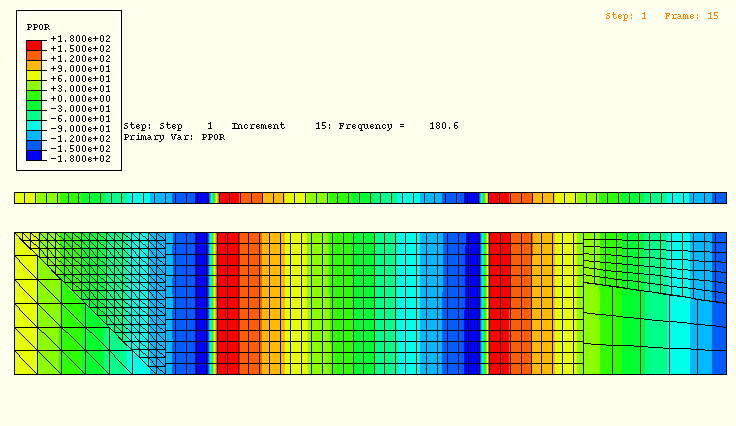
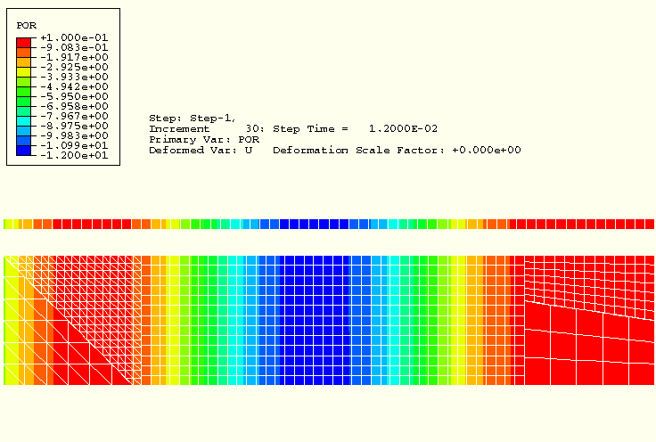
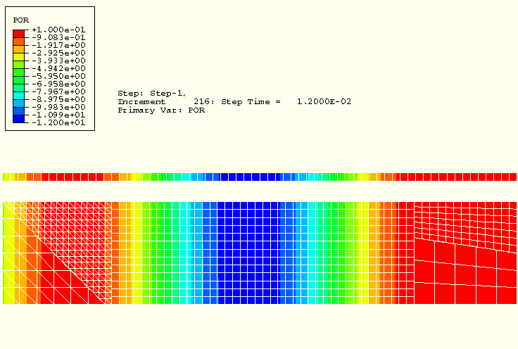
Each analysis shows good agreement between the reference domain and the domain using tie constraints. The resonant frequencies and mode shapes for the *FREQUENCY analysis also agree very well, although more modes exist in the frequency band of interest for the wider, lower domain. Figure 1.10.5–2 shows the phase angle of the acoustic pressure (variable PPOR) at 180.6 Hz in the steady-state response. Since PPOR is the phase angle of the complex-valued solution, defined from –180° to 180°, sharp differences in contour plot color appear at the negative solution values of greatest magnitude. Although the field is continuous, these sharp color lines can be thought of as defining wavefronts in the solution. The wavefronts in the contour plot appear at the same locations for the reference and tied meshes, and the tie constraints do not distort the waves. Figure 1.10.5–3 and Figure 1.10.5–4 show the acoustic pressure magnitude (variable POR) in the transient case at 0.012 seconds, before the wave has reached the end of the meshes. Again, the wavefronts coincide for the tied and reference meshes, and the constraints do not distort the solution.
Steady-state problems.
Transient problem.
Transient analysis.

Figure 1.10.5–2 Pressure phase at 180.6 Hz, using *STEADY STATE DYNAMICS, DIRECT.

Figure 1.10.5–3 Pressure magnitude at 0.012 seconds, using *DYNAMIC.

Figure 1.10.5–4 Pressure magnitude at 0.012 seconds, using *DYNAMIC, EXPLICIT.
