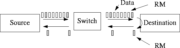
Figure 1:
ABR Traffic Management Model: Source, Switch, Destination and Resource Management Cells
Raj Jain, Shivkumar Kalyanaraman, Sonia Fahmy and Rohit Goyal
Department of Computer and Information Science
The Ohio State University
Columbus, OH 43210-1277
E-mail: {
jain,shivkuma,fahmy,goyal}@cse.wustl.edu
and Seong-Cheol Kim
Samsung Electronics Co. Ltd.
Chung-Ang Newspaper Bldg.
8-2, Karak-Dong, Songpa-Ku
Seoul, Korea 138-160
Email: kimsc@metro.telecom.samsung.co.kr
Abstract
Available bit rate (ABR) service has been developed to support data applications over asynchronous transfer mode (ATM) networks. The network continuously monitors its traffic and provides feedback to the source end systems. This article explains the rules that the sources have to follow to achieve a fair and efficient allocation of network resources.
A key distinguishing feature of ATM networks as compared to current packet networks is that they offer multiple qualities of services (QoS). TM4.0 specifies five classes of services: constant bit rate (CBR), real-time variable bit rate (rt-VBR), non-real time variable bit rate (nrt-VBR), available bit rate (ABR), and unspecified bit rate (UBR). Of these, the ABR service has been specifically designed for efficient handling of data traffic.
One of the challenges in designing ATM traffic management was to maintain the QoS for various classes while attempting to make maximal use of network resources. This is what distinguishes traffic management from the ``congestion control'' problem of the past. Congestion control deals only with the problem of reducing load during overload. Traffic management deals not only with load reduction under overload or load increase during underload but, more important, tries to ensure that the QoS guarantees are met in spite of varying load conditions. Thus, traffic management is required even if the network is underloaded. This article provides insights into the development of ABR traffic management and explains the reasons behind various decisions. The basic model used is introduced in the next section.
Figure 1:
ABR Traffic Management Model: Source, Switch, Destination and Resource Management Cells
The ABR traffic management model is called a ``rate-based end-to-end closed-loop'' model. The model is called ``rate-based'' because the sources send data at a specified ``rate.'' This is different from current packet networks (for example, TCP), where the control is ``window based'' and the sources limit their transmission to a particular number of packets. The ABR model is called ``closed-loop'' because there is a continuous feedback of control information between the network and the source. If more sources become active, the rate allocated to each source is reduced. The model used for CBR and VBR traffic, on the other hand, is ``open-loop'' in the sense that rates are negotiated at the beginning of the connection and do not change dynamically. Finally, the model is called ``end-to-end'' because the control cells travel from the source to the destination and back to the source. The alternative of ``hop-by-hop'' control in which each switch would give feedback to the previous switch was considered and not accepted due to its complexity. However, one can achieve the hop-by-hop control in TM4.0 using the virtual source/virtual destination (VS/VD) feature discussed later in this section.
When there is a steady flow of RM cells in the forward and reverse directions, there is a steady flow of feedback from the network. In this state, the ABR control loop has been established and the source rates are primarily controlled by the network feedback (closed-loop control). However, until the first RM cell returns, the source rate is controlled by the negotiated parameters, which may or may not relate to the current load on the network. The virtual circuit (VC) is said to be following an ``open-loop'' control during this phase. This phase normally lasts for one round-trip time (RTT). As we explain later, ABR sources are required to return to the open-loop control after long idle intervals. Traffic sources that have active periods (bursts) when data is transmitted at the allocated rate and idle periods when no data is transmitted are called ``bursty sources'' Open-loop control has a significant influence on the performance of bursty traffic particularly if it consists of bursts separated by long idle intervals.
There are three ways for switches to give feedback to the sources. First, each cell header contains a bit called Explicit Forward Congestion Indication (EFCI), which can be set by a congested switch. This mechanism is a modification of the DECbit scheme [ 12]. Such switches are called ``binary'' or ``EFCI'' switches. Second, RM cells have two bits in their payload, called the Congestion Indication (CI) bit and the No Increase (NI) bit, that can be set by congested switches. Switches that use only this mechanism are called relative rate marking switches. Third, the RM cells also have another field in their payload called explicit rate (ER) that can be reduced by congested switches to any desired value. Such switches are called explicit rate switches.
Explicit rate switches normally wait for the arrival of an RM cell to give feedback to a source. However, under extreme congestion, they are allowed to generate an RM cell and send it immediately to the source. This optional mechanism is called backward explicit congestion notification (BECN).
Switches can use the VS/VD feature to segment the ABR control loop into smaller loops. In a VS/VD network, the switches additionally behave both as a (virtual) destination end system and as a (virtual) source end system. As a destination end system, it turns around the RM cells to the sources from one segment. As a source end system, it generates RM cells for the next segment. This feature can allow feedback from nearby switches to reach sources faster, and allow hop-by-hop control as discussed earlier.
During the development of the RM specification, all numerical values in the specification were replaced by mnemonics. For example, instead of saying ``every 32nd cell should be an RM cell'' the specification states ``every Nrm$th$ cell should be an RM cell.'' Here, Nrm is a parameter whose default value is 32. Some of the parameters are fixed while others are negotiated. This being a tutorial (and not a standard document), we have reverted back to the default values of these parameters. This makes it easier to understand. A complete list of parameters used in the ABR mechanism is presented in Table 1. The parameters are explained as they occur in our discussion.
| Label | Expansion | Default Value |
|---|---|---|
| PCR | Peak Cell Rate | - |
| MCR | Minimum Cell Rate | 0 |
| ACR | Allowed Cell Rate | - |
| ICR | Initial Cell Rate | PCR |
| TCR | Tagged Cell Rate | 10 cells/s |
| Nrm | Number of cells between FRM cells | 32 |
| Mrm | Controls bandwidth allocation | 2 |
| between FRM, BRM and data cells | ||
| Trm | Upper Bound on Inter-FRM Time | 100 ms |
| RIF | Rate Increase Factor | 1/16 |
| RDF | Rate Decrease Factor | 1/16 |
| ADTF | ACR Decrease Time Factor | 0.5 ms |
| TBE | Transient Buffer Exposure | 16,777,215 |
| CRM | Missing RM-cell Count | $\lceil$ TBE/Nrm $\rceil$ |
| CDF | Cutoff Decrease Factor | 1/16 |
| FRTT | Fixed Round-Trip Time | - |
Note that in-rate and out-of-rate distinction applies only to RM cells. All data cells in ABR should have CLP set to 0 and must always be within the rate allowed by the network.
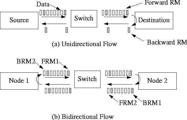
Figure 2:
Forward and Backward Resource Management Cells (FRMs and BRMs)
The Current Cell Rate (CCR) field is used by the source to indicate to the network its current rate. Some switches may use the CCR field to determine a VC's next allocation while others may measure the VC's rate and not trust CCR. The minimum cell rate (MCR) field is redundant in the sense that like PCR, ICR, and other parameters it does not change during the life of a connection. However, its presence in the RM cells reduces number of lookups required in the switch.
The ER, CI and NI fields are used by the network to give feedback to the sources. The ER field indicates the maximum rate allowed to the source. When there are multiple switches along the path, the feedback given by the most congested link is the one that reaches the source.
Data cells also have an Explicit Forward Congestion Indication (EFCI) bit in their headers, which may be set by the network when it experiences congestion. The destination saves the EFCI state of every data cell. If the EFCI state is set when it turns around an RM cell, it uses the CI bit to give (a single bit) feedback to the source. When the source receives the RM cell from the network, it adjusts its ACR using the ER, CI, NI values, and source parameters.
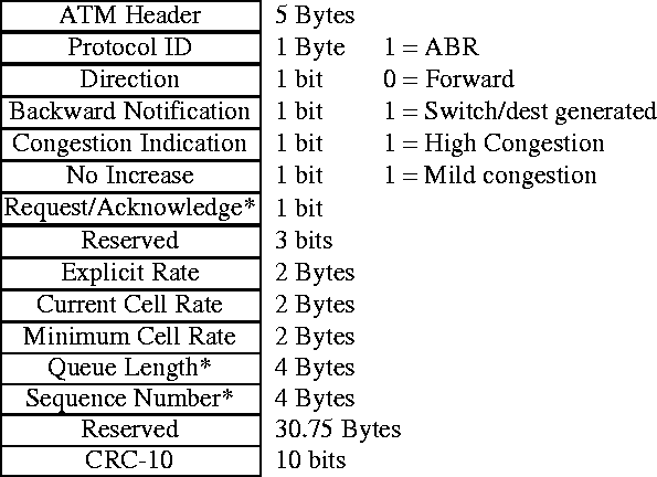
Figure 3:
{Resource Management (RM) Cell Fields
All rates (e.g., ER, CCR, and MCR) in the RM cell are represented using a special 16-bit floating point format, which allows a maximum value of 4,290,772,992 cells per second (1.8 terabits per second). During connection setup, however, rate parameters are negotiated using an 24-bit integer format, which limits their maximum value to 16,777,215 cells per second or 7.1 Gb/s.
TM4.0 specifies 13 rules that the sources have to follow. This section discusses each rule and traces the development and implications of certain important rules. In some cases the precise statement of the rule is important. Hence, the source and destination rules are quoted from the TM specification [ 1] in appendix A. A list of abbreviations and their expansions is provided in appendix~\ref{app:acronyms}.
First, the sources are required to send an FRM after every 31 cells. However, if the source rate is low, the time between RM cells will be large and network feedback will be delayed. To overcome this problem, a source is supposed to send an FRM cell if more than 100 ms has elapsed since the last FRM. This introduces another problem for low rate sources. In some cases, at every transmission opportunity the source may find that it has exceeded 100 ms and needs to send an FRM cell. In this case, no data cells will be transmitted. To overcome this problem, an additional condition was added that there must be at least two other cells between FRMs.
An example of the operation of the above condition is shown in the figure 4. The figure assumes a unidirectional VC (i.e., there are no BRMs to be turned around). The figure has three parts. The first part of the figure shows that, when the source rate is 500 cells/s, every 32nd cell is an FRM cell. The time to send 32 cells is always smaller than 100 ms. In the second part of the figure, the source rate is 50 cells/s. Hence 32 cells takes 640~ms to be transmitted. Therefore, after 100~ms, an FRM is scheduled in the next transmission opportunity (or slot). The third part of the figure shows the scenario when the source rate is 5 cells/s. The inter-cell time itself is 200~ms. In this case, an FRM is scheduled every three slots, i.e., the inter-FRM time is 600~ms. Since Mrmis 2, two slots between FRMs are used for data or BRM cells.
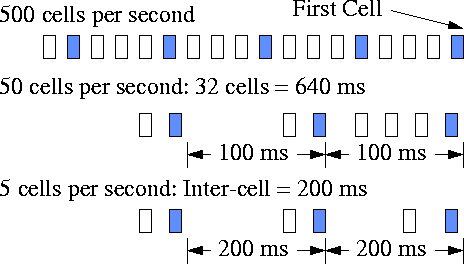
Figure 4:
Frequency of forward RM cells.
Second, a waiting BRM has priority over waiting data, given that no BRM has been sent since the last FRM. Of course, if there are no data cells to send, waiting BRMs may be sent.
Third, data cells have priority in the remaining slots.
The second and third part of the this rule ensure that BRMs are not unnecessarily delayed and that all available bandwidth is not used up by the RM cells.
Figure 5illustrates the scheduling of FRMs, BRMs and data cells. In the first slot, an FRM is scheduled. In the next slot, assuming that a turned around BRM is awaiting transmission, a BRM is scheduled. In the remaining slots data is scheduled. If the rate is low, more FRMs and BRMs may be scheduled.
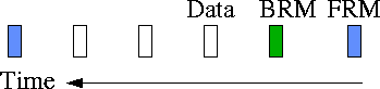
Figure 5:
Scheduling of forward RM, backward RM, and data cells.
The frequency of FRM is determined by parameters Nrm, Trm, and Mrm, whose default values are 32, 100 ms, and 2, respectively. During the debate on credit vs rate based alternatives for traffic management [ 5], the rate based group selected a default value of 32 for Nrm. This ensured that the control overhead was equivalent to that of credit based alternative which claimed an overhead of approximately 6\%. During normal operation 1/32th or 3\% of all cells are FRM cells. Similarly, another 3\% of cells are BRM cells resulting in a total overhead of 6\%.
In practice, the choice of Nrm affects the responsiveness of the control and the computational overhead at the end systems and switches. For a connection running at 155 Mb/s, the inter-RM cell time is 86.4~$\mu$s while it is 8.60~ms for the same connection running at 1.55 Mb/s. The inter-RM interval determines the responsiveness of the system. While most end-systems and switches will do ABR computations in hardware, it has been shown that it is possible to do them in software on a Pentium$^{TM}$ system provided Nrm is set to 192 or higher on a 155 Mb/s link.
The timeout interval is set by the ACR Decrease Time Factor (ADTF). This parameter can be negotiated with the network at connection setup. Its default value is 500 ms.
This simple rule was the cause of a big debate at the Forum. It is intended to solve the problem of ACR retention. If a source sends an RM cell when the network is not heavily loaded, the source may be granted a very high rate. The source can then retain that rate and use it when the network is highly loaded. In fact, a source may set up several VCs and use them to get an unfair advantage. To solve this problem, several so called use it or lose it(UILI) solutions were proposed. Some of them relied on actions at the source while others relied on actions at the switch. The source based solutions required sources to monitor their own rates and reduce ACR slowly if was too high compared to the rate used.
UILI alternatives were analyzed and debated for months because they have a significant impact on the performance of bursty traffic that forms the bulk of data traffic. The ATM Forum chose to standardize a very simple UILI policy at the source. This policy provided a simple timeout method (using ADTF as the timeout value) which reduces ACR to ICR when the timeout expires. Vendors are free to implement additional proprietary restraints at the source or at the switch. A few examples of such possibilities are listed in the Informative Appendix I.8 of the specification [ 1]. See also [ 4], [ 2], [ 11].
Normally under steady state, sources should receive one BRM for every FRM sent. Under congestion, BRM cells may be delayed. If a source has sent CRM FRM cells and has not received any BRM, it should suspect network congestion and reduce its rate by a factor of CDF. Here, CRM (missing RM cell count) and CDF (cutoff decrease factor) are parameters negotiated at the time of connection setup. BECN cells generated by switches (and identified by BN=1) are not counted as BRM.
When rule 6 triggers once, the condition is satisfied for all successive FRM cells until a BRM is received. Thus, this rule results in a fast exponential decrease of ACR. An important side effect of this rule is that unless CRM is set high, the rule could trigger unnecessarily on a long delay path. CRM is computed from another parameter called transient buffer exposure (TBE) which is negotiated at connection setup. TBE determines the maximum number of cells that may suddenly appear at the switch during the first round trip before the closed-loop phase of the control takes effect. During this time, the source will have sent TBE/Nrm RM cells. Hence,

The fixed part of the round-trip time (FRTT) is computed during connection setup. This is the minimum delay along the path and does not include any queueing delay. During this time, a source may send as many as ICR $\times$ FRTT cells into the network. Since this number is negotiated separately as TBE, the following relationship exists between ICR and TBE:
In negotiating TBE, the switches have to consider their buffer availability. As the name indicates, the switch may be suddenly exposed to TBE cells during the first round trip (and also after long idle periods). For small buffers, TBE should be small and vice versa. On the other hand, TBE should also be large enough to prevent unnecessary triggering of rule 6 on long delay paths.
It has been incorrectly believed that cell loss could be avoidedby simply negotiating a TBE value below the number of available buffers in the switches. Jain et al. [ 10] showed that it is possible to construct workloads where queue sizes could be unreasonably high even when TBE is very small. For example, if the FRM input rate is $x$ times the BRM output rate (see Figure 6), where $x$ is less than CRM, rule 6 will not trigger but the queues in the network will keep building up at the rate of $(x-1)\times \mbox{ACR}$ leading to large queues. The only reliable way to protect a switch from large queues is to build it in the switch allocation algorithm. The ERICA+ algorithm [ 7] is an example of one such algorithm.
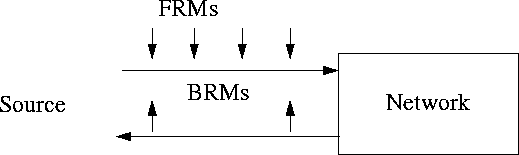
Figure 6:
Source Rule 6 does not trigger if BRM flow is maintained
Observe that the FRTT parameter which is the sum of fixed delays on the path is used in the formula for ICR. During the development of this rule, an estimate of round trip time (RTT), including the fixed and variable delays was being used instead of FRTT in the ICR calculation. We argued that RTT estimated at connection setup is a random quantity bearing little relation to the round trip delays during actual operation [ 9]. Such parameter setting could trigger source Rule 6 unnecessarily and degrade performance. Hence, the Forum decided to use FRTT parameter instead of RTT.
Note that it is possible to disable source Rule 6, by setting CDF to zero.
First, if the new ER is very high compared to current ACR, switching to the new ER will cause sudden queues in the network. Therefore, the amount of increase is limited. The rate increase factor (RIF) parameter determines the maximum allowed increase in any one step. The source cannot increase its ACR by more than RIF $\times$ PCR.
Second, if there are any EFCI switches in the path, they do not change the ER field. Instead, they set EFCI bits in the cell headers. The destination monitors these bits and returns the last seen EFCI bit in the CI field of a BRM. A CI of 1 means that the network is congested and that the source should reduce its rate. The decrease is determined by rate decrease factor (RDF) parameter. Unlike the increase, which is additive, the decrease is multiplicative in the sense that \[ \mbox{ACR} \LA \mbox{ACR}(1-\mbox{RDF})\] It has been shown that additive increase and multiplicative decrease is sufficient to achieve fairness [ 6]. Other combinations such as additive increase with additive decrease, multiplicative increase with multiplicative decrease, and multiplicative increase with additive increase are unfair.
The no-increase (NI) bit was introduced to handle mild congestion cases. In such cases, a switch could specify an ER, but instruct that, if ACR is already below the specified ER, the source should not increase the rate. The actions corresponding to the various values of CI and NI bits are listed in the table.
| NI | CI | Action |
|---|---|---|
| 0 | 0 | ACR <- Min(ER, ACR + RIF x PCR, PCR) |
| 0 | 1 | ACR <- Min(ER, ACR - ACR x RDF) |
| 1 | 0 | ACR <- Min(ER, ACR) |
| 1 | 1 | ACR <- Min(ER, ACR - ACR x RDF) |
If there are no EFCI switches in a network, setting RIF to 1 allows ACRs to increase as fast as the network directs it. This allows the available bandwidth to be used quickly. For EFCI networks, or a combination of ER and EFCI networks, RIF should be set conservatively to avoid unnecessary oscillations.
Once the ACR is updated, the subsequent cells sent from the source conform to the new ACR value. However, if the earlier ACR was very low, it is possible that the very next cell is scheduled a long time in the future. In such a situation, it is advantageous to ``reschedule'' the next cell, so that the source can take advantage of the high ACR allocation immediately [ 8].
If the destination has internal congestion, it may reduce the ER or set the CI or NI bits just like a switch. Observe that this rule is used in the VS/VD configuration where the virtual destination is bottlenecked by the allowed rate in the next segment. In any case, the ER is never increased.
Note that there is no specified limit on the rate of such ``turned around'' out-of-rate RM cells. However, the CLP bit is set to 1 in the out-of-rate cells, which allows them to be selectively dropped by the switch if congestion is experienced.
Shivkumar Kalyanaraman [StM]is a doctoral candidate in Computer Sciences at the Ohio state University. He received his B.Tech. degree from the Indian Institute of Technology, Madras, India in July 1993. He received his M.S. degree from the Ohio State University in 1994. His research interests include broadband networks, transport protocols, congestion control, distributed systems, and performance analysis. He is a co-inventor of two patents, and has co-authored several papers and ATM forum contributions in the field of ATM congestion control.
Sonia Fahmy [StM]received her B.S. degree from the American University in Cairo, Egypt, in June 1992, and her M.S. degree from the Ohio State University in March 1996, both in Computer Science. She is currently a Ph.D. student at the Ohio State University. Her main research interests are in the areas of broadband networks, congestion control, performance analysis, distributed computing and programming languages. She co-authored several papers and ATM Forum contributions.
Rohit Goyalis a Ph.D. student with the Department of Computer and Information Science at the Ohio State University, Columbus. He received his BS in Computer Science from Denison University, Granville. His work has been published in several ATM forum contributions and Technical Reports. His other interests include Distributed Systems, Artificial Intelligence, and Performance Analysis. Rohit is a member of Phi Beta Kappa, Who's who among students in American Colleges, Sigma Xi, Pi Mu Epsilon, Sigma Pi Sigma and the Phi Society.
Seong-Cheol Kimreceived his Ph.D. from Polytechnic University in 1995 in electrical engineering. Since 1995 he has been with Samsung Electronics as a principal engineer. His research interests include traffic control, congestion control, and multimedia and ATM communications.