| Steven Bosch, Pradosh Kharel, Eli Katz (A paper written under the guidance of Prof. Raj Jain) |
Download |
Unmanned Aerial Vehicle (UAV) technology combined with wireless mobile networking is a growing area of research with promising preliminary results. This technology could be used to quickly deploy a wireless network over a large area during emergencies where typical networks might fail. In this paper, we implement and perform experiments to test an implementation of a mobile wireless network. We also perform experiments to test the seamless handover capability of the network as well as test the performance of common applications like Voice over IP (VoIP) while using UAVs. Using Raspberry Pis and OpenWrt to create a wireless distributed network with seamless handover, we were able to get average stall periods of 1.615 seconds for a VoIP call and 37.26 seconds for file transfers using Secure Copy Protocol (SCP). We also measured signal strength and packet loss of the wireless network when deployed on a UAV.
seamless handover, Raspberry Pi, OpenWrt, UAV, WDS, VoIP, SCP, DD-WRT, wireless network, Zoiper, Asterisk
Experiment Design and Analysis of a Mobile Aerial Wireless Mesh Network for Emergencies, Seamless Handover among WiFi Access Points on Raspberry
Aerial wireless mobile networking is a growing area of research with promising preliminary results. In the last several years, Unmanned Aerial Vehicles (UAVs) have become affordable and reliable, but their potential as infrastructure for wireless networks remains untapped. UAV-based networks would be more maneuverable and adaptable to their circumstances than existing infrastructure. One important potential application is a disaster-relief scenario where permanent communication systems have been rendered inoperable. Deploying a UAV-based network in that situation could support rescue efforts by allowing civilians, aid workers, and law enforcement to communicate.
However, one of the primary challenges associated with UAV technology is its heavy power consumption. The need for large batteries reduces the carrying capacity of the UAV and limits its flight time. In an aerial network, UAV units would have to circulate due to battery constraints. Building on the prior research of Dali [Dali14] and Yijian [Yijian16], our goal was to implement a seamless handover procedure in a mobile aerial network to allow units to be switched out without interrupting service. This can be done by implementing WDS (Wireless Distribution System). WDS is a system that enables interconnectivity of access points with the same backend network. WDS is ideal for our project since the coverage area can be quickly expanded simply by adding new UAVs with on-board routers and it provides seamless handover, as desired.
The remainder of this paper is organized in the following way: In Section 2, we describe the structure of our wireless network and design choices for the server, routers, and clients. In Section 3, we describe the implementation and verification of the seamless handover procedure. We then describe the setup, testing, and results of the wireless network and handover procedure when deployed on UAV units in Section 4. Finally, Section 5 presents ideas for future work in this area of research.
In a disaster-relief scenario, UAV units bearing routers could be deployed to cover a broad area. The routers would act as access points (APs) that rescue workers or civilians could connect to for communication and emergency procedures. The UAV routers would mediate the connection between user devices like computers or smart phones through a central base router on the ground. This ground router would relay data as a communications server that establishes connections between clients and transfers data between them. This topology is depicted in Figure 1. In this section we discuss the implementation details of our network’s server and clients, the software we use for our Voice over IP (VoIP) communication, and the routers that define our network topology.

The communications (VoIP) server controls the transmission of data packets to enable VoIP communication between devices on the network. Our implementation of this server consists of the Asterisk framework running on a consumer Dell laptop with the CentOS 7 operating system. CentOS 7 is the latest version of the CentOS Linux distribution, a free and widely-used operating system. Asterisk is a free, open-source communications framework that allows a computer to operate as a VoIP gateway. To manage the Asterisk system, we used the FreePBX web-based GUI. Installation and configuration instructions for Asterisk can be found in Appendices 9.2 and 9.3. In the next subsection we describe our choice of software for the clients of our network.
The communication system we used in this project is VoIP. VoIP is a group of technologies for making phone calls using an internet connection rather than using the traditional public switched telephone network. VoIP has many associated benefits, such as cheap or free calls that utilize existing Internet access and voice communication in areas without cellular network coverage. These technologies and associated protocols can be used by smartphones, computers, and other internet-connected devices [Fcc01]. In a disaster-relief scenario, the portability that VoIP offers allows clients on any platform to communicate over the network without having to rely on cellular communications infrastructure, which may not be intact or reliable given the circumstances. We used the Session Initiation Protocol (SIP) to coordinate the establishment and termination of the voice call. SIP can operate on many transport-layer protocols, such as User Datagram Protocol (UDP), Transmission Control Protocol (TCP), or Stream Control Transmission Protocol (SCTP) [Ietf01]. Our network may not be entirely reliable due to its mobile nature, and voice communication can be intelligible with missing packets, so the protocol needs to be tolerant of missing packets. Therefore, UDP was a desirable protocol for our experiment’s transmissions because it is connectionless -- clients do not maintain a persistent connection to transmit data.
For the VoIP client, we used Zoiper: a free, secure, cross-platform internet telephony application. Zoiper allows users to have a dedicated extension within the Asterisk communication network. Extensions set up on the Asterisk server can be linked to client devices running Zoiper. We were able to successfully configure and use Zoiper on the iOS and OSX client devices we used for this project. Instructions for Zoiper client installation and configuration can be found in Appendix 9.4. These client devices connect to our network through Raspberry Pis that act as routers, which we discuss in the next subsection.
A key component of the overall project is the implementation of a wireless network that provides connectivity to devices in a large area. Since the UAVs have limited battery, we can expect certain access points to become unavailable abruptly. In such a scenario, we would want disconnected clients to transfer connections over to available access points. To achieve this, we use the Wireless Distribution System (WDS) to broadcast a single network using multiple access points. When an access point goes down, clients do not have to go over the initial handshaking procedure when connecting to active access points, and the network interruption is limited [Openwrt01].
For our ground station, we used a Linksys WRT54GL router running DD-WRT, an open-source Linux based firmware. For the UAV routers, we used Raspberry Pis with OpenWrt as wireless, mobile access points. Raspberry Pis are light, low cost devices that make them ideal for our project. OpenWrt is an open source Linux based firmware that can be installed on the Raspberry Pi to convert it to a network router. To enable wireless on the Raspberry Pi, we used Alfa AWUS036NHR v2 USB WiFi adapters. This implementation of WDS using Raspberry Pis and OpenWrt is based on previous research [yijian16] [Yijian16].
Our network is simple and uses many components that are either open-source and free or inexpensive. Low price is a big factor not only because it allowed us to conduct this experiment and allows others to recreate it, but also because if this network were to be deployed over a disaster area, rescue efforts would require many UAVs to provide service to a broad area. Furthermore, the implementation of these devices and protocols are straightforward and easy to use. With the network now implemented, we will now discuss the goals of our research and the tests conducted.
As discussed in Section 1, the major component of WDS of interest is seamless handover. In this section, we describe our implementation of a WDS network to test the effects of handover on large file transfers and VoIP calls. We begin this section by giving an overview of seamless handover and test the network’s capability by interrupting our client’s connection. We then look at a test of handover while performing a file transfer and another test while performing a VoIP call. The steps required to configure the Raspberry Pis and the base router are given in Appendix 9.1.
To test our WDS network for handover, we first setup the network shown in Figure 2 using two Raspberry Pis. The Client machines were notebooks. All of the network connections are wireless except the link between the VoIP server and the router.

To test handover of clients, we first setup the network shown in Figure 2 using two Raspberry Pis. The client machines were MacBook Pros. All of the network connections are wireless except the link between the VoIP server and the router.


We also tested the effects of handover on a large file transfer using Secure Copy Protocol (SCP). SCP requires a TCP connection, so the client will take some time to confirm that its connection is no longer working before attempting to establish a connection through a new router. Therefore, we can expect some delay time when disrupting the connection before it is re-established. Using the same network shown in Figure 2, we initiated a file transfer between Clients 1 and 2 and turned off the Raspberry Pi 1 AP radio during the middle of the transfer. We then used Wireshark, a packet sniffing software, to capture and analyze the handover based on TCP sequence IDs. An example of this is shown in Figure 4.

Figure 4 shows the sequence number of TCP packets over time. For this particular experiment, the AP was disabled at around the 10-second mark. This disruption resulted in a delay between the transfer of successive TCP packets (stall time). Continued transfer was finally re-established around the 26 second mark. We repeated this procedure for 10 file transfers, the results of which are shown below in Table 1.
| SCP Transfer Number | Stall Time (seconds) |
|---|---|
| 1 | 68.79 |
| 2 | 16.55 |
| 3 | 18.68 |
| 4 | 63.98 |
| 5 | 29.06 |
| 6 | 18.75 |
| 7 | 75.12 |
| 8 | 27.64 |
| 9 | 26.83 |
| 10 | 27.24 |
As we can see from Table 1, the stall times are very large, going as high as 68 seconds. The average stall time was 37.26 seconds. Such a long delay can result in failed transfers. And while we were able to perform our file transfers, this protocol is not well-suited to our needs. In the next section, however, we shall discuss our main goal of performing handover during a VoIP call, which sends its data via UDP.
A realistic use of an aerial WDS network could be VoIP calls, especially if deployed during emergencies where traditional networks might have failed. We tested the seamless handover using the softphone software Zoiper and the same network as shown in Figure 2. We established calls between the two clients, turning off the AP radio on the Raspberry Pi in the middle of the call. The handover was then analyzed using captured Zoiper packets. Figure 5 shows an example of the packet trace of the handover in Wireshark.

In Figure 5, we can see Address Resolution Protocol (ARP) packets (Packet 4375) as soon as the radio is disabled. These packets are signify the client looking for a new connection. Regular transmission of VoIP data resumes later on in the trace (Packet 4410). The difference in time between these two packets give us an estimate of the sound delay in Zoiper. We repeated this procedure 10 times, the results of which are shown below in Table 2. In these 10 trials, the average transmission delay is 1.615 seconds. While such a delay is noticeable during the call, it will not interfere greatly with any communication, and the call is not dropped.
| VoIP Call Number | Stall Time (seconds) |
|---|---|
| 1 | 1.873 |
| 2 | 0.830 |
| 3 | 1.773 |
| 4 | 2.003 |
| 5 | 1.472 |
| 6 | 2.312 |
| 7 | 1.613 |
| 8 | 1.033 |
| 9 | 1.256 |
| 10 | 1.986 |
Our tests show that the handover process has an average stall time of 37.26 seconds for file transfers, which is indeed a very long interruption. We also noticed that some transfers failed entirely which leads us to conclude that our network is not suitable for large file transfers. On the other hand, the stall time for VoIP calls is quite low at 1.615 seconds. Most importantly, however, the calls are not dropped. With tests performed on our network in a lab setting, we are now able to explore the mobility aspect of our wireless mobile network, which we discuss in the next section.
The primary goals of this research were to ensure that VoIP calls could be successfully established and maintained over UAV-based access points and that the calls would not be dropped during a handover procedure. To that end, we conducted experiments whereby we repeated tests performed in Section 3 with the Raspberry Pis and AP radios that were powered by battery packs, all of which were secured to the underside of the UAVs. In this section we describe the setup of our experiment as well as design considerations; tests conducted in a controlled, indoor environment to verify procedure and to provide a baseline for the results of outdoor tests; and the tests when the network was airborne and their results.
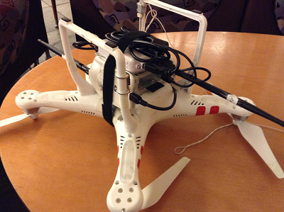
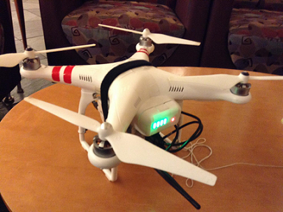
When designing this experiment, several different factors contributed to the choice of equipment, such as weight and battery life. We used the DJI Phantom 2, a UAV with many desirable properties. The Phantom 2 is lightweight (weighing 1000 g) and capable of flying while carrying an additional 300 g. It also has a flat surface on the bottom, which stands 4 inches off the ground, allowing third-party devices to be easily mounted. Furthermore, the Phantom 2 has a built-in GPS that enables the unit to hover in place, automatically correcting for wind when receiving adequate signal from GPS satellites. The Phantom 2’s primary shortcoming is its short battery life, which is intrinsic to all modern UAV technology. With a fully charged battery, the quadcopter can remain airborne for only about 25 minutes [Dji01]. This limitation was a primary factor in our design for the payload to consist only of the router, antennas, and their power supply.
For the router we used a WDS-enabled Raspberry Pi with two Alfa high-gain 2000 mw 802.11 b/g/n wireless network adaptors with 5 dBi antennas for communication with client devices and the ground router. The DJI Smart Battery cannot be used to power the Raspberry Pi or antennas, so an additional power supply was necessary. Our choice of batteries was significant, as we needed to supply adequate power to the long-range network adapters while still keeping the aircraft light enough to achieve flight. The Raspberry Pi is powered by a 5 V micro USB supply, so we used Docooler Portable USB Emergency AA Battery Powered Chargers to convert the 3 V output from 2 standard 1.5 V AA batteries to 5V output [Raspberrypi01]. To minimize weight, we conducted preliminary flights with only one USB charger; however, we noticed that the signal strength with the UAV was very low and our devices lost connectivity shortly after takeoff. The batteries quickly became overheated, since they could not sustainably provide the necessary current draw. By attaching two of the chargers in series, we were able to use 4 batteries to supply the devices with adequate power, and our connections subsequently remained stable. The power pack was then able to outlast the UAV’s power supply and consequently was no longer the limiting factor of the flight time.
Before testing our implementation in the air, we performed an experiment on the ground to verify that our network was correctly configured. Our network was set up the same way as in Figure 2, except with the Raspberry Pis connected to the UAVs. This test would also provide an idea of appropriate distances for our aerial experiment, as the unimpeded horizontal distance between UAVs and clients should translate perfectly to vertical distance outdoors. We placed our UAV with the Raspberry Pi, antennas, and battery packs at one end of a long corridor inside a campus building. We then positioned our base station router, server, and Zoiper-enabled OSX clients down the hall from the UAV. We used InSSIDer (WiFi scanning software) to measure the signal strength of the UAV-mounted router at intervals of 50 feet. Our results are shown in Table 3.
| Distance (feet) | Signal Strength (5dBi Antenna) (dBm) |
|---|---|
| 50 | -45 |
| 100 | -52 |
| 150 | -64 |
| 200 | -67 |
Signal strength is a useful metric for connectivity because sufficient strength is necessary for effective transmission. Signal strength decreases with distance and different devices have different sensitivities. For instance, Apple iOS devices have a “trigger threshold” of -70 dBi, under which the client automatically drops the connection. In our tests, we saw that the signal from the UAV was strong enough for iOS devices to maintain a connection, up to 200 feet away. However, there is a large drop in strength of 12 dBi after 100 feet, which shows the increasing difficulty of establishing connections with increasing distance. With one client connected to the base station and the other connected to the UAV router, we also attempted to place a Zoiper call at each distance. In all cases, the signal strength was sufficient to establish and to maintain a VoIP call. Having shown that our network was capable of handling connections at distances up to 200 feet in a controlled environment, we then moved on to conducting the experiments while airborne.
After confirming that calls could be made in an indoor setting, we conducted a series of flight experiments with the UAVs. Since we needed a large open space to safely fly the UAVs, we performed our experiments at nighttime on the parking lot of the Washington University in St. Louis campus. We used the same network topology that we used in the lab tests, connecting one Zoiper client to the ground router and the other client to a UAV’s router.
Our first experiment was to measure signal strength and packet loss with the airborne routers. For this experiment, we required only one UAV through which to send our packets. In order to measure the altitude of the UAV, we attached a kite string to its underside and taped distance markers along the length of the string. After securing the Raspberry Pi, antennas, and battery packs to the UAV, we flew the craft to a position directly above the base station. Throughout the experiment, we flew the UAV to different heights in increments of 50 feet. At each position, we measured the signal strength of the sky router using InSSIDer and attempted to make a Zoiper call between the connected clients.
We also performed a series of data throughput measurements using iPerf 3, a network testing tool. We used iPerf’s standard configuration of sending bursts of 16 UDP datagrams every second for 10 seconds to make our measurements. Repeating this procedure 5 times, we determined an average successful datagram transmission rate at varying altitudes. The results are shown in Table 4.
| Altitude (feet) | > Signal Strength (dBi) | Datagrams Received (%) |
|---|---|---|
| 50 | -45 | 75 |
| 100 | -53 | 91 |
Using the 5 dBi antennas on the ground router, we were able to conduct Zoiper calls up to 100 feet. However, upon increasing the altitude beyond this point, no connection could be established between the clients. While the client devices maintained a steady connection with the sky and ground routers, no data could be successfully transmitted between the endpoints.
We then tested the seamless handover procedure in the air. In order to do so, we recreated the network of our previous tests with 2 airborne routers. We connected one client to a UAV-mounted router and one client to the base router, positioning both UAVs at an altitude of 50 feet above the base router. With the UAVs at that height, the Zoiper call we established had sufficient packet throughput for intelligible voice communication. By checking the OpenWrt configuration, we then determined with which router the client was associated and remotely disabled its radio. The client quickly associated with the other OpenWrt access point. Voice data was momentarily lost while the client switched access points, but the delay was under 5 seconds and the call was maintained. We repeated the procedure at 100 feet, and while the quality of the call was dramatically lower, the handover procedure was still successful. Above 100 feet, the packet loss was once again too great for a successful Zoiper call.
We repeated these experiments several times in varying weather conditions with the same results. Based on our successful lab tests, the antennas received adequate power from the battery packs, and as such it is unlikely that insufficient current caused the connection loss. A more likely explanation could be the motion of the UAVs while the clients attempted to connect. High crosswinds made it difficult to keep the UAVs both centered over the ground router and positioned at a constant altitude.
While the poor conditions proved to be a consistent issue for the duration of the project, however, we overcame this obstacle by performing many flight tests and gathering data in small increments whenever the weather momentarily improved. Maintaining the security and balance of the UAV attachments also proved challenging. Whenever the Phantom 2 senses it is off balance, it automatically prevents attempts to increase its altitude until it can fly properly. Initial flights failed until we achieved a balanced configuration of the attachments, which were secured to each other and to the UAV with lightweight tape and Velcro. We found it helpful to attach the payload and test for balance before inserting the UAVaE s battery, as the internal controller automatically compensates for the batteryaE s non-uniform weight distribution.
Since the performance of the UAV-mounted routers was poor, we would like to perform similar trials with antennas of different types and strengths (e.g., higher gain, directional) to compare results. Ideally we would like our routers and UAVs higher in the air both to provide signal to a broader area and to avoid obstacles, such as tall buildings or trees. Another metric we would like to explore is transmission speed. With high rates of data transfer, other services besides voice calls (e.g., video, large file transfers) could be sent through our routers, which could be used for purposes such as providing live video of a disaster area or two-way video communication between victims and rescue services.
In this paper we presented an aerial, wireless mobile network topology that can be implemented using quadcopters, Raspberry Pis, and OpenWrt. This network is cheap to implement, uses software that is open-source and cross-platform, and has reliable signal strength. We were able to establish VoIP calls through this network while routers mounted on the UAVs were flown up to heights of 100 feet. However, this network does have high packet loss at higher altitudes. We also successfully tested seamless handover and were able to get accurate timings on the stall period for multiple applications during client handover. Most importantly, we showed that seamless handover during VoIP calls on our network caused a slight delay but was successful in maintaining the call.
[Yijian16] Yijian Li, "Seamless Handover among WiFi Access Points on Raspberry Pi" 2016. 4 Apr. 2016. http://www.cse.wustl.edu/~jain/theses/yijianms.htm
[Dali14] Dali Ismail, "Experiment Design and Analysis of a Mobile Aerial Wireless Mesh Network for Emergencies," M.S. Project Report, Washington University in Saint Louis, May 2014,http://www.cse.wustl.edu/~jain/theses/dali_ms.htm
[Openwrt01] "Client Mode Wireless [OpenWrt Wiki]." 2009. 4 Apr. 2016. https://wiki.openwrt.org/doc/howto/clientmode
[Openwrt02] "Raspberry Pi [OpenWrt Wiki]." 2015. 4 Apr. 2016 https://wiki.openwrt.org/toh/raspberry_pi_foundation/raspberry_pi
[Openwrt03] "Chaos Calmer Repository" 2015. 4 Apr. 2016 https://downloads.openwrt.org/chaos_calmer/15.05/brcm2708/bcm2709/packages/base/
[Ddwrt01] "Linksys WRT54GL - DD-WRT Wiki." 2009. 4 Apr. 2016 http://www.dd-wrt.com/wiki/index.php/Linksys_WRT54GL
[Dji01] "Phantom 2 - The Spirit Of Flight" 2016. 4 April 2016 http://www.dji.com/product/phantom-2
[Raspberrypi01] "Raspberry Pi FAQs - Frequently Asked Questions" 2016. 4 April 2016 https://www.raspberrypi.org/help/faqs/
[Fcc01] "Voice Over Internet Protocol | Federal Communications Committee" 2016. April 4, 2016 https://www.fcc.gov/general/voice-over-internet-protocol-voip
[Ietf01] "RFC 4168 - The Stream Control Transmission Protocol (SCTP) as a Transport for the Session Initiation Protocol" 2005. 4 April 206 https://tools.ietf.org/html/rfc4168
[Apple01] aEoeWireless roaming reference for enterprise customers - Apple SupportaE 2015. April 17, 2016. https://support.apple.com/en-us/HT203068
AP: Access Point
ARP: Address Resolution Protocol
dBi: Decibel (isotropic)
DHCP: Dynamic Host Configuration Protocol
LAN: Local Area Network
SCP: Secure Copy
SCTP: Stream Control Transmission Protocol
SSH: Secure Shell
SIP: Session Initiation Protocol
TCP: Transmission Control Protocol
UAV: Unmanned Aerial Vehicle
UDP: User Datagram Protocol
VoIP: Voice over IP
WDS: Wireless Distribution System
In this section, we go over the steps required to create a wireless network with WDS and seamless handover. For our project, we used a Linksys WRT54GL router as our main base station.


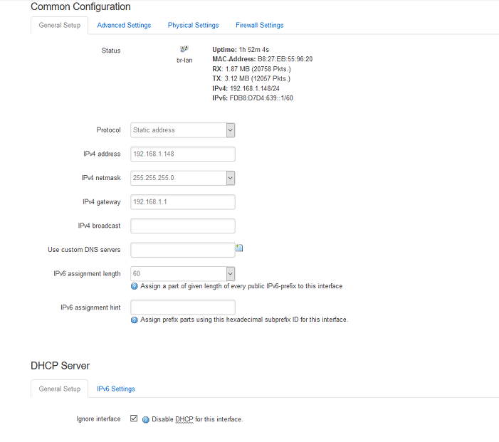
The same steps can be repeated for any number of Raspberry Pis.