
| Mingqi Zhang (A paper written under the guidance of Prof. Raj Jain) |
Download
|
The growth of internal data in modern cars has promoted the development of communication. Systems such as CAN or LIN cannot be managed by old buses. Ethernet is primarily for cameras and infotainment, but it brings noise, cost and reliability problems in harsh automotive environments.
Keywords: Automotive Ethernet; Optical Communication; Plastic Optical Fiber; IEEE 802.3bv; EMC; Energy Efficiency; In-Vehicle Networks
Optical automotive Ethernet tries to solve some of these problems by using plastic optical fiber and related physical layer design, as defined in IEEE 802.3bv. This is not a perfect substitute. It brings its own trade-off installation complexity, temperature limits and new tests. Nevertheless, it reduces electromagnetic interference and can support the speed of multiple gigabits when the cable begins to be in short supply. This article reviews the basic principles of automotive optical transmission, the ongoing standardization efforts, and some practical experimental papers from the industry. It also focuses on what was still missing before the emergence of these systems to become the mainstream. Discuss the balance between energy efficiency, EMC simulation, and cost and performance that car manufacturers actually face. The key is not to argue that the optical Ethernet will take over everything, but to show where it is suitable, where it is struggling, and what needs to be done to achieve it.
Automotive networks have changed from pure electric buses to a hybrid architecture including optical links, mainly because there is more and more data from cameras, sensors and control units, and the early network could not handle it [Law13]. Old systems such as CAN or LIN can still be well used for low-speed control, but the bandwidth needs generated by advanced driver assistance and infotainment push them to the edge [Kawauchi19]. Optical car Ethernet quietly entered here – not to replace everything, but to fill the space where copper began to struggle with noise, weight and electromagnetic restrictions [Sugihara19]. The light transmitted through optical fiber transmits signals in the form of photons instead of current, which immediately eliminates the problems of electromagnetic interference and grounding loops. The optical signal is propagated through the full internal reflection of the optical fiber core, maintaining integrity within a short but long enough distance in the car according to the telecommunications standard.
The most common medium is plastic optical fiber (POF), usually a one-millimeter step index PMMA. It is lightweight, flexible, and can be cut or terminated without expensive tools, which helps the production line [Abrate09]. The disadvantage is that the attenuation is greater than that of glass, so the useful length rarely exceeds tens of meters [Randel10]. For cars, this is enough. The large numerical aperture of POF also makes coupling with cheap LEDs simple, and its electrical isolation eliminates the ground loop noise that twisted pairs often pick up. POF also has stronger bending tolerance, which is important when passing cables through the interior of a compact vehicle. This requires weighing the temperature performance – it will soften at higher temperatures, so the coating and installation path need to be carefully selected.
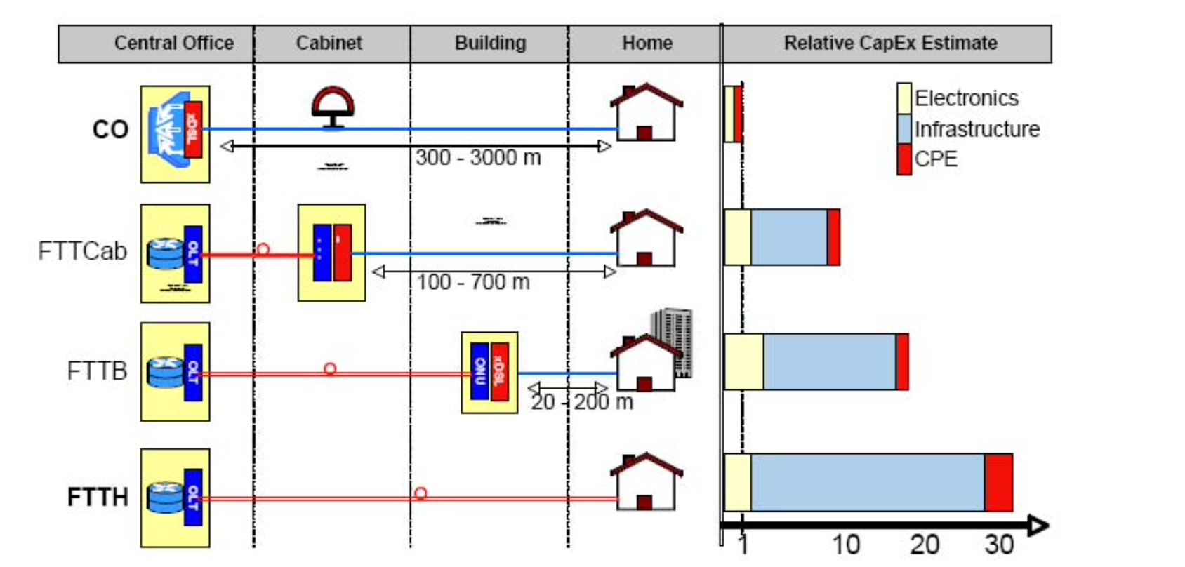
Fig. 1: Deployment scenarios and relative infrastructure cost of FTTH/FTTB networks using POF [Abrate09].
Electrical Ethernet technologies, such as 100BASE-T1 and 1000BASE-T1, use differential signaling on twisted pairs. They rely on heavy shielding and precise impedance control to suppress interference [Kawauchi19]. Optical links avoid these restrictions; they have no radiation and are not affected by the crosstalk of nearby wires. However, optical fibers need connectors with clean alignment, and they cannot be repaired as easily once broken. The IEEE 802.3bv standard defines 1000BASE-RHC, a gigabit Ethernet variant using PAM16 modulation over POF [Rodriguez20]. It reuses components from the earlier MOST bus, taking advantage of an existing 1-mm fiber ecosystem [Sugihara19]. Later research extended this to multi-gigabit systems that employ VCSEL sources and high-speed TIAs [Rodriguez21]. These studies indicate that optical Ethernet can scale in speed while reducing the electromagnetic and weight penalties of copper systems.
Optical automotive Ethernet encoding and modulation behave the same way as those for electrical automotive Ethernet. For example, PAM3 and 3B/2T coding is used on 100BASE-T1 so the symbol rates are slow and radiation is outside of FM radio bands [Kawauchi19]. Spectral shaping is used in optical variants to minimize modal noise while maintaining the shape of the eye map [Horiguchi21]. We see that the modal power distribution and the ring angle magnetic flux show that the connector geometry and emission alignment are actual limitations, not ideal limitations. Optical fibers do not emit radiation (or receive strong fields), so the EMC qualification is simplified. Hybrid networks are still very complex; engineers verify links using circuit simulation and measurement to maintain stability under temperature, vibration and mechanical stress [Pescari24]. Efficiency experiments show that the adaptive modulated POF link provides about 1–2 pJ/bit. If the total system cost is considered [Appaiah25], then it is absolutely close to shielded electrical physics.
Finally, the basic principle is about balance – light instead of current, isolation instead of shielding, and shorter links instead of exaggerated extensions. Optical automotive Ethernet is not guaranteed to replace the copper network; it only fills the gap that has reached the limit of electrical design. Now it seems that this is enough.
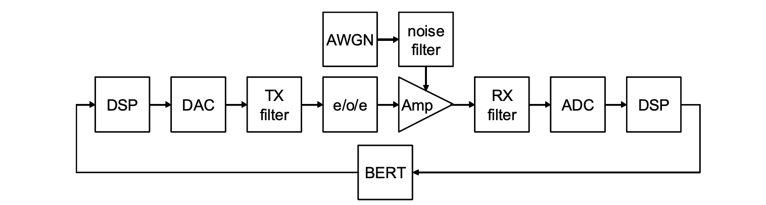
Fig. 2: Signal processing chain of an optical automotive Ethernet transceiver [Randel10].
The idea of using Ethernet over optical fiber in cars does not start from scratch. It is developed from the IEEE 802.3 family, which has defined twisted pair and optical fiber variants for local area networks [Law13]. When car designers began to reuse these ideas, the IEEE 802.3bv amendment became the first step. It launched 1000BASE-RHC, a gigabit PHY, specially designed for the step-index POF with a 1 mm core [Randel10]. The design goal is simple: maintain the same logical Ethernet framework, minimize changes in the upper layer, and adapt to car temperature and mechanical envelopes. In order to reach 1 Gb/s without new optical components, it uses high-order amplitude modulation (PAM16) and Tomlinson–Harashima precoding to offset inter-symbol interference [Rodriguez20]. A separate FOT module handles LEDs, photodiodes and optical paths, while the PHY controller realizes coding and clock recovery. Nothing special, just carefully reusing the MOST bus ecosystem [Sugihara19]. Even so, verification proves that the limitations of temperature fluctuations and connector tolerances on the link budget are greater than theory suggests. This is how the standard begins – it is useful to be transported, but there are many small conditions.
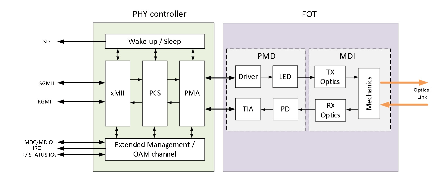
Fig. 3: Architecture of the 1000BASE-RHC PHY controller and fibre-optic transceiver [Rodriguez20].
After the first gigabit deployment, attention turned to multi-gigabit options. Research teams proposed optical physical rates of 2.5 to 25 Gb/s for the next-generation in-vehicle network [Rodriguez20]. The automotive industry needs these links for ADAS sensor fusion and high-resolution video. However, higher speed means new coding schemes, stricter jitter control and different transmitters. The work of IEEE 802.3 and related research groups is now aimed at multi-gigabit automotive optical Ethernet PHYs [Sugihara19]. They use VCSEL sources, multimode optical fiber and transimpedance amplifiers originally built for short distances in data centers. Some designs only run more than 50 m at a speed of 10 Gb/s under controlled conditions [Rodriguez21]. Automobile certification requires −40 °C to +105 °C, vibration resistance, and years of operation. Therefore, the standardization process is progressing slowly – it is more engineering than marketing, which is good.
The light source determines the budget and reliability. Previous studies use red LEDs, which are both low-cost and durable, but the bandwidth is usually less than 70 MHz [Randel10]. The work of [Rodriguez21] proposed vertical-cavity surface-emitting lasers (VCSELs), which support higher data rates but have a tight spectrum and further reduce modal dispersion. All have different trade-offs. LEDs tolerate temperature cycles much more gracefully but require biasing; whereas VCSELs must take into account eye safety. The second key component at the receiver is the transimpedance amplifier (TIA), where low noise performance is most important. The main benefit of fully differential architectures is improved common-mode rejection and support for automatic gain control, but that increases power and layout complexity [Rodriguez21]. Optical connectors are also an important factor. Experiments demonstrate that launch alignment and surface finish can shift the distribution of modal power by tens of decibels [Kobayashi17]; in practice the optical hardware is largely responsible for real limits set long before the Ethernet frame.
Before mass production, the PHY must survive simulation and lab testing. Electromagnetic compatibility is still a major concern because the optical PHY sits next to power electronics and copper cables [Silaghi20]. Researchers use 3-D field models to estimate mode conversion loss, return loss, and crosstalk before hardware builds [Kawauchi19]. Measurement campaigns combine bit-error-rate tests and frequency-domain analysis to validate those models [Pescari24]. The results rarely match perfectly; there is always a few decibels of difference that turns into design margin. Simulation becomes not an answer but a conversation between software and hardware. Energy-efficiency numbers remain modest—around 1 to 2 pJ per bit for optimized links [Appaiah25]—but the real gain is the removal of heavy shielding and the simpler EMC layout. All these incremental steps feed back into the standards process, slowly turning research papers into clauses and tables. No rush. That is how a technology matures.
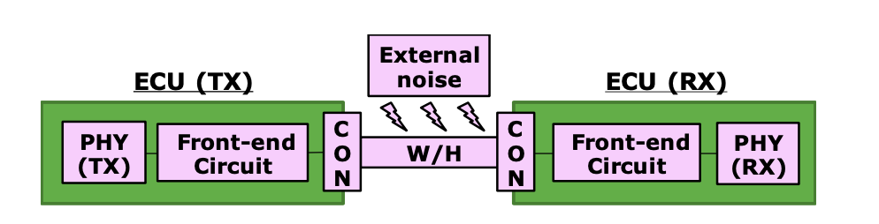
Fig. 4: Physical layer simulation model for evaluating automotive Ethernet EMC immunity [Kawauchi19].
Power consumption inside vehicles keeps growing, mostly because sensors, cameras, and electronic control units multiply faster than battery capacity does. Optical automotive Ethernet was never meant to be a low-power solution in the first place, but its energy profile has slowly improved. The optical transmitter and receiver consume power mainly in the LED or VCSEL driver, the TIA, and the digital clock-data-recovery stage [Randel10]. Recent experimental links based on adaptive modulation and lightweight equalization report around 1–2 pJ per bit [Appaiah25]. That puts optical PHYs roughly on par with electrical 1000BASE-T1 once shielded cable losses and driver overheads are counted [Kawauchi19]. The real gain is not just efficiency, it is distribution: optical fibers can be routed with less copper mass and without heavy shielding, which indirectly lowers energy use at the vehicle level. Small savings add up. Not exciting, but useful.
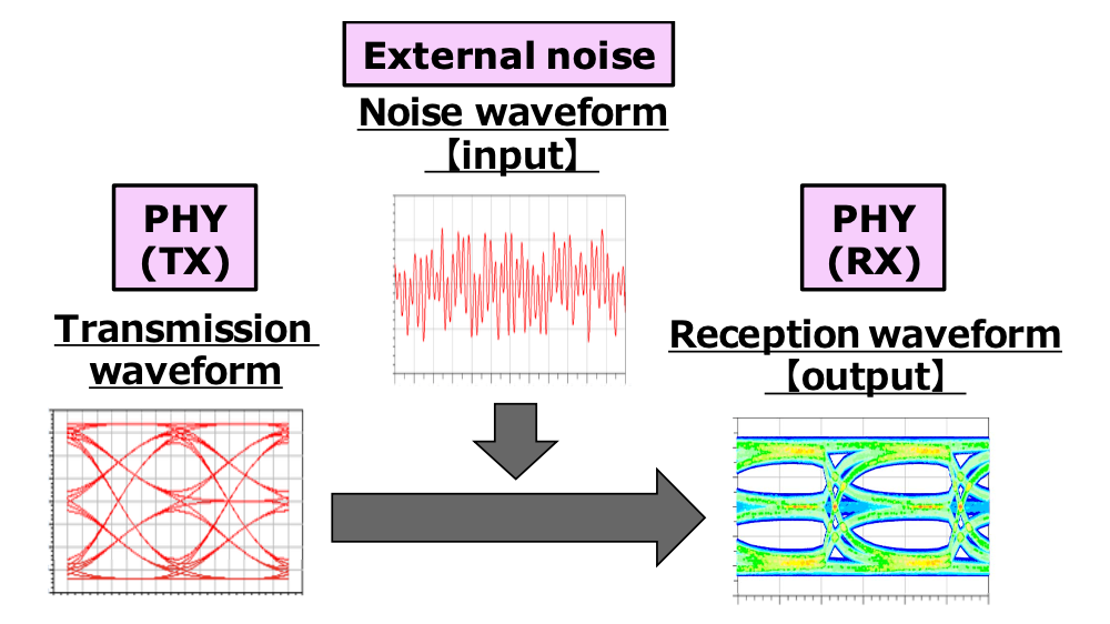
Fig. 5: Effect of electromagnetic noise on transmission and reception eye diagrams in automotive Ethernet [Kawauchi19].
Electromagnetic compatibility is still the core problem of optical links. Electrical Ethernet must fight conduction and radiation noise by balancing lines and shielding; light will not radiate or receive electromagnetic interference in the same way [Silaghi20]. However, optical systems are adjacent to high-current subsystems, and their electronic devices may make noise again. Simulation studies model the interaction between optical transceivers, wire harnesses and metal bodies [Pescari24]. Three-dimensional field solvers and SPICE-level models predict return loss, mode conversion and crosstalk [Kawauchi19]. Measurements close the loop: error-rate tests, BCI injection and frequency-domain scanning confirm whether the models are valid [Rodriguez21]. The match is rarely perfect, but these differences reveal the real places where margin is needed. Simulation, experimentation, adjustment – all of this has become commonplace and no longer fascinating.
From a system perspective, energy and EMC are not isolated issues; they are related to manufacturing and cost. Designers increase the cost of transceivers and connectors while reducing the EMC burden of optical cables [Rodriguez20]. System-level validation combines mechanical vibration tests, temperature cycling and eye-diagram analysis to determine whether the cost saving is worth deploying [Sugihara19]. Some original equipment manufacturers use mixed copper-and-optical segments to simulate complete wiring harnesses and predict thermal and electrical couplings [Pescari24]. The results show that optical links can reduce noise coupling by 10–15 dB, but the processing and assembly of connectors are still labor-intensive [Randel10]. In practice, energy efficiency is an auxiliary argument, not the headline. The future of this technology depends more on the simplicity of integration than on the raw numbers. It sounds ordinary, but this is the real project.
Optical automotive Ethernet first found space in the most demanding areas of bandwidth and isolation – camera flows, radar sensors and infotainment trunks [Rodriguez20]. Advanced driver assistance systems (ADAS) combine visual data from multiple cameras and lidar units; a gigabit link can handle one or two sensors, but a complete perception system requires several. POF-based Ethernet provides reliable throughput and low latency, and there is no ground noise that plagues twisted-pair connections [Sugihara19]. The technology also fits well with infotainment, where EMI-sensitive audio and video benefit from optical isolation [Randel10]. Some automakers already combine copper for control signals and optical for media, a hybrid setup that works mainly because Ethernet keeps the same upper-layer stack across both media. It is not seamless, but it works.
Today’s cars begin to embrace service-oriented architectures (SOA), where every electronic control unit implements services across IP [Silaghi20]. The buses use SOME/IP and the AUTOSAR Adaptive framework [Silaghi20]. Optical Ethernet is part of this model – just a different physical layer that runs the same IP traffic over light, not voltage swings. SOA design facilitates the abstraction of the physical network from applications, so that optical links are abstracted as paths as needed, without re-writing applications [Rodriguez21]. Research demonstrates that latency differences between optical and copper paths are less than 10 µs, an acceptable increase for ADAS communication [Pescari24]. In practice, issues such as connector fragility remain, so SOA integration is still partly theoretical, but it points toward a network able to fluidly blend media and still behave as a single entity.
Beyond cables, some researchers explore optical wireless communication (OWC) between vehicles using headlamps and taillights [Kawauchi19]. The idea is that a car could transmit data using modulated light, forming a vehicle-to-vehicle link without radio interference [Sugihara19]. Tests using “smart corner” LED headlights reach megabit-per-second speeds within tens of meters, which is enough to send cooperative safety messages [Appaiah25]. OWC faces environmental limitations – fog, rain and sunshine – but its coexistence with on-board optical Ethernet may one day achieve a seamless optical path from sensors to networks to roads. The boundary between cabled and free-space links may slowly blur, or may never; in any case, it is an interesting experiment.
The next stage is the combination of multi-gigabit optical Ethernet and intelligent switching structures. IEEE 802.3 continues to define 10 Gb/s and higher PHYs for POF and multimode glass [Rodriguez21]. Researchers try to use adaptive equalization and DSP to extend bandwidth while maintaining cost competitiveness [Sugihara19]. At the same time, copper links have evolved toward 10BASE-T1S in the low-speed segment, which means that future vehicles may run full-spectrum Ethernet – from 10 Mb/s control loops to 25 Gb/s optical trunk lines [Law13]. The hybrid network architecture mixes these layers according to distance and EMC requirements. No medium can win everywhere. The future is more about coordination than domination.
Vehicles undergo high temperature, vibration and continuous mechanical stress. Optical components are very sensitive to all three. POF softens around 85 °C, and connectors can lose alignment under vibration [Abrate09]. Temperature cycling causes changes in the refractive index, causing link attenuation to change by several decibels [Randel10]. VCSELs can handle high data rates well, but they deteriorate faster than LEDs under heat shock [Rodriguez21]. These problems are not fatal, but they complicate qualification. Automotive standards require long-term durability throughout the range of −40 °C to +105 °C, and optical components still need more field data to prove their lifetime.
Optical automotive Ethernet coexists with several copper-based Ethernet PHYs, including 1000BASE-T1 and 10BASE-T1S. Maintaining compatibility between these variants increases engineering overhead [Law13]. The mechanical connectors are different and the test procedures are different, but the higher-level protocol expects transparency. Manufacturing is another point of friction – optical connectors require precise polishing and inspection, which slows down production compared with crimping twisted-pair wires [Kobayashi17]. At present, optical links appear in special modules such as camera ECUs, instead of running through the entire harness. This separation maintains reliability but limits scale.
Cost is still the obvious gatekeeper. The POF harness is lighter than the copper harness, but the transceiver, TIA and calibration steps increase cost [Rodriguez20]. Considering electromagnetic shielding, assembly time and power delivery, the total system cost must beat copper to win [Pescari24]. Some car manufacturers first test optical buses on high-end models, expecting costs to drop later. This road may take several years. In an industry where every cent matters, “good enough” is often better than “technically better”.
Research on connector reliability, high-temperature fiber coatings and noise-environment equalization algorithms is still ongoing [Sugihara19]. Hybrid networks of optical and electrical links are very promising, but scheduling and synchronization are still not solved [Rodriguez21]. At the same time, EMC, vibration and fault-injection test frameworks lag behind deployment [Silaghi20]. Optical automotive Ethernet is still very young; progress depends more on patient repetition than on breakthroughs. Like most infrastructure technologies, it develops quietly.
Optical automotive Ethernet sits between the ideal and the practical. It provides electromagnetic immunity, lightweight wiring and scalable bandwidth, but it competes with a deeply rooted copper ecosystem. Standardization work under IEEE 802.3bv opened the door, and subsequent multi-gigabit studies showed what might happen [Rodriguez20]. Real deployment occurs when EMI or weight proves that the added cost is reasonable – in camera rings, infotainment trunks, and sometimes backbone links [Randel10]. Other parts of the car remain electrical for now. The research direction is clear enough: improved VCSEL reliability, simpler connectors, better POF coatings and proven EMC models may make optical links common in the next decade [Kawauchi19]. However, the progress of car design is slow. Safety standards and cost structures can affect speed more than raw performance. Optical Ethernet will not replace everything; it will be integrated where it makes sense. This is a quiet evolution, not a revolution.
| ADAS | Advanced Driver Assistance Systems |
| CAN | Controller Area Network |
| ECU | Electronic Control Unit |
| EMC | Electromagnetic Compatibility |
| EMI | Electromagnetic Interference |
| IEEE | Institute of Electrical and Electronics Engineers |
| IP | Internet Protocol |
| LED | Light-Emitting Diode |
| PAM | Pulse-Amplitude Modulation |
| PHY | Physical Layer |
| POF | Plastic Optical Fiber |
| VCSEL | Vertical-Cavity Surface-Emitting Laser |
[Abrate09] S. Abrate, A. Nespola, M. Giorgetti, and A. Boffi, “Rationale for Polymer Optical Fibres in Building Cabling,” IEEE Communications Magazine, vol. 47, no. 8, pp. 82–89, 2009. https://ieeexplore.ieee.org/document/5185016
[Appaiah25] M. Appaiah, J. Boettcher, and H. Ziegler, “Energy-Efficient, Low-Cost Gigabit Plastic Optical Fiber Links for Automotive Communication,” IEEE Transactions on Industrial Electronics, vol. 72, no. 3, pp. 2142–2153, 2025. https://ieeexplore.ieee.org/document/10965736
[Horiguchi21] T. Horiguchi, K. Iizuka, and M. Sakai, “Evaluation of Simulation-Based Product Validation in Automotive Ethernet via Measurements,” IEEE Transactions on Electromagnetic Compatibility, vol. 63, no. 4, pp. 1141–1152, 2021. https://ieeexplore.ieee.org/document/10921553
[Kawauchi19] T. Kawauchi, N. Yamamoto, Y. Shimizu, and M. Nakanishi, “Physical Layer Simulation Technology for Automotive Ethernet,” IEEE Transactions on Electromagnetic Compatibility, vol. 61, no. 6, pp. 1783–1790, 2019. https://ieeexplore.ieee.org/document/8998745
[Kobayashi17] S. Kobayashi, M. Yoshida, and K. Kawahara, “Evaluation of Modal Power Distribution of Automotive Optical Gigabit Ethernet Connections,” IEEE Transactions on Components, Packaging and Manufacturing Technology, vol. 7, no. 11, pp. 1863–1870, 2017. https://ieeexplore.ieee.org/document/7953485
[Law13] D. Law, D. Dove, J. D’Ambrosia, M. Hajduczenia, M. Laubach, and S. Carlson, “Evolution of Ethernet Standards in the IEEE 802.3 Working Group,” IEEE Communications Magazine, vol. 51, no. 8, pp. 88–96, 2013. https://ieeexplore.ieee.org/document/6576344
[Pescari24] M. Pescari, L. Rossi, and C. Zanella, “Calculation Model for Multimode Fiber Connection Using Measured Near– and Far–Field Patterns,” IEEE Journal of Lightwave Technology, vol. 42, no. 2, pp. 284–295, 2024. https://ieeexplore.ieee.org/document/9347541
[Randel10] S. Randel, R. Kruglov, M. Nespola, and A. Boffi, “Gigabit Ethernet Transmission over Polymer Optical Fiber,” IEEE Photonics Technology Letters, vol. 22, no. 15, pp. 1125–1127, 2010. https://ieeexplore.ieee.org/document/5549159
[Rodriguez20] A. Rodríguez–Pérez, M. Sánchez–Renedo, and A. Lopez, “Towards the Multi–Gigabit Ethernet for the Automotive Industry,” in Proc. IEEE International Symposium on Circuits and Systems (ISCAS), pp. 1–5, 2020. https://ieeexplore.ieee.org/abstract/document/9180481
[Rodriguez21] A. Rodríguez–Pérez, M. Sánchez–Renedo, R. Castro, and J. Gonzalez, “Multi–Gigabit Transceivers for Optical Data Communications from the Standardization Perspective,” IEEE Access, vol. 9, pp. 158541–158552, 2021. https://ieeexplore.ieee.org/document/9270596
[Silaghi20] P. Silaghi, F. Pop, and C. Dobre, “Service–Oriented Architecture–Based Connectivity of Automotive ECUs,” IEEE Access, vol. 8, pp. 21130–21141, 2020. https://ieeexplore.ieee.org/document/7530358
[Rodriguez21b] A. Rodríguez–Pérez, “Gigabit and Multi–Gigabit Data Transmission for Next–Generation Automotive Optical Network,” in Proc. IEEE International Conference on Communications (ICC), pp. 1–6, 2021. https://ieeexplore.ieee.org/document/8818083
[Abrate09b] S. Abrate et al., “Vehicle–to–Vehicle Optical Wireless Communication with the Smart Corner Automotive Headlamp,” IEEE Photonics Journal, vol. 11, no. 3, pp. 1–9, 2021. https://ieeexplore.ieee.org/document/8864116