
ATM, from the start, was designed to be a multimedia, multiservice technology. Though the ATM has been accepted by the marketplace for its ability to deliver high speed data services, till the recent past its potential for deploying for voice services was overlooked. With the competitiveness of today's market, the network operators and the service providers have been continuously striving to reduce operating costs and lift network efficiency. They recognized that significant economic benefits can be achieved once the data traffic and voice traffic are integrated onto a single network. Since ATM has been around for around a decade claiming to be a multimedia technology, most of the service providers have started installing single ATM infrastructure to support voice, video, and data transfer. Initially, there were a lot of technical issues that were unaddressed, which basically hampered the growth of vtoa. Thanks to the efforts of the ATM Forum and its members, these issues have been addressed and now it is possible to build and operate an ATM network to meet the needs of various types of voice application.
The document is organized as follows. Section 2 of this paper deals with the various design considerations and issues that are to be pondered on before installing an ATM network for voice. The section also covers how the design issues are addressed by the recent standards in voice over ATM. Section 3 concentrates on various standards that are getting evolved on VTOA. We would be looking on some of the successful products that are manufactured by various vendors for successful transmission of voice over ATM in section 4.
With the standards are in place it is now possible for packet switching techniques like Frame Relay or ATM to deliver high quality speech. Some of the intrinsic advantages ATM has over other network technologies are listed below.
Though ATM is equipped with transferring voice over the network efficiently, ATM onto the desktop would not be popular enough until the turn of the millennium. The reasons being, there are enough competing technologies, like 100-Mbps Ethernet/Gigabit Ethernet that provide similar services with minimal infrastructure upgrade to be done. But, when WAN is considered, ATM has its own niche over its competing technologies for the same reasons we discussed above. While designing and engineering voice over an ATM WAN, there are set of design issues which needs to be addressed. Some of them are:
A packetised approach to transmit voice faces a number of technical challenges, which spring from the real-time or interactive nature of the voice traffic. Some of the challenges that need to be addressed are:
2.1.1 Echo
It is a phenomenon, where the transmitted voice signal gets reflected back due to unavoidable impedance mismatch and four-wire/two-wire conversion between the telephone handset and the communication network.. It can, depending on the severity, disrupt the normal flow of conversation. Its severity depends on the round-trip time delay. It is found if the round-trip time delay is more that 30 ms, the echo becomes significant, which makes the normal conversation difficult.
2.1.2 End-to-End Delay
Voice is most sensitive to delay and mildly sensitive to variations in delay (jitter). It is highly critical that the delay is kept at a bare minimum to hold an interactive communication end-to-end. It has been found [ Jain97] that delay can have two effects on communication performance. Delay can interfere with the dynamics of voice communication, in the absence of noticeable echo, whereas in the presence of noticeable echo, increasing delay makes echo effects worse. When the delay reaches above 30 ms, echo cancellor circuits are required to control the echo. Once the echo cancellor circuits are in place, network delays can be allowed to reach upto 150 ms without further degrading the voice quality.
According to the ITU-T Recommendation G.114 the following delay limits for one-way transmission time for connections with adequate echo control are considered allowable.
| Delay | Acceptability. |
| 0 - 150 ms | acceptable to most user application. |
| 150 - 400 ms | acceptable when the impact on quality is aware of. |
| 400 ms | unacceptable |
Delay occurs in ATM networks because of one or more of the following reasons.
a) Packetization Delay (or cell construction delay):
It is the time taken to fill in a complete packet/cell before it is transmitted. Normal PCM (Pulse Code Modulation) encoded voice samples arrive at the rate of 64Kbps, which means it takes around 6 ms to fill the entire 48 byte payload of the ATM cell. The problem can be addressed either with partially filled cells or by mulitplexing several voice calls into a single ATM VCC (Virtual Circuit Channel).
b) Buffering Delay
Sometimes, due to the delay in transit some cells might arrive late. If this happens, SAR (Segmentation And Reassembling) function provided by the Adaptation layer might have to under-run with no voice data to process which would be resulted as gaps in the conversation. To prevent this the receiving SAR function would accumulate a buffer of information before starting the reconstruction. In order to ensure no under-runs occur the buffer size should be kept in such a way it exceeds the maximum predicted delay. The size of the buffer translates into delay, as each cell must progress through the buffer on arrival at the emulated circuit's line rate. This implies that the Cell Delay Variation (CDV) has to be controlled within the ATM network.
c) Encoding Delay
This is the processing time taken by the compression algorithms to encode the analog signal to digital form.
2.1.3 Silence Suppression
Voice in its inherent nature is variable. It is found that on an average, human voice has a speech activity factor of about 42%. There are pauses between sentences and words with no speech in either direction. Also voice communication is half-duplex. i.e., one person is silent while the other speaks. One can take advantage of these two characteristics to save bandwidth by halting the transmission of cells during these silent periods. This is known as silence suppression.
2.1.4 Compression Algorithms.
ADPCM (Adaptive Differential Pulse Code Modulation) and CELP (Code Excited Linear Prediction) are the two major compression algorithms that are used. Now, LD-CELP (Low Delay CELP), a derivative of CELP is the most commonly used compression algorithm used on any voice signal. This has been standardized by ITU as ITU G.728. This provides a toll quality voice at 16kbps with low encoding/decoding delay. The Table 2 [
NewBridge98] below compares the various compression techniques for their bandwidth usage, MIPS (millions of instructions per second) and delay.
| Algorithm | Bandwidth | MIPS (C5x DSP) | Total Codec Delay (msec) | Application. |
| PCM | 64 kbit/s | n/a | 0.25 | PSTN |
| ADPCM (G.726) | 32 kbit/s | 10 | 0.25 | PSTN, cordless phones |
| CS-ACELP (G.729) | 8 kbit/s | 30 | 25 | VoFR, VoATM, VoIP |
| CS-ACELP Annex A (G.729A) | 8 kbit/s | 20 | 25 | VoFR, VoATM, VoIP |
| LD-CELP (G.728) | 16 kbit/s | 40 | 1.25 | PSTN |
| MP-MLQ (G.723.1) | 5.3/6.3 kbit/s | 30 | 67.5 | Multimedia and VoIP |
This relates to the efficient utilization of resources and the transfer of control and signaling information. There are two parts in a voice call - the actual voice samples and the signaling information, like dialed number, the on-hook/off-hook status of the call, and other routing and control information. This signaling can be encoded and may be sent as Common Channel signaling (CCS), where signaling information from different channels is aggregated into a single signaling channel, and Channel Associated signaling (CAS), where signaling information is embedded within each discrete voice channel.
The transport of voice demands that the data be synchronized between the speaker and the listener. There are two standard mechanisms that are used to achieve synchronization between point-to-point applications. They are Adaptive Clocking and the Synchronous Residual Time Stamping (SRTS). These mechanisms work by adjusting the clock rate at one end of the circuit based on the clock rate of the other end.
The above mentioned mechanisms work effectively only in the master-slave environment or point-to-point communication. When multipoint services are in operation, it is not possible for a slave to adjust its clock based on two or more difference signals coming from different master sites. For multipoint service, it is easy to adopt an externally synchronised model where each node in the network is synchronised to some external clock source.
Back to Table of ContentsVarious applications are available for the transport of voice over an ATM network. Each application has differing requirements for voice transport based on what class of network operators they are defined in. Let us discuss the three major classes of network operators [ ATMForum99].
National or International Operators typically have an extensive PSTN service operating over SDH/SONET or PDH infrastructure. When bandwidth is limited there will be a requirement to integrate voice and data traffic, for reasons of efficiency into a single ATM network. Within the local loop, ATM may be a valuable solution for the carriage of voice and data to business premises.
Alternate Carriers or Value Added Network Suppliers take up licenses to provide communication services in competition with the incumbent national operators. Instead of having their own transmission infrastructure, they buy bandwidth from the primary operator. Cost and limited availability of bandwidth demand ATM's efficiency, and integration of voice and data services. Example of alternate carriers is cellular phone operators.
Private/Enterprise networks buy bandwidth at commercial (retail) rates and achieve the most they can with the resources on hand. Such organizations will have already deployed a TDM network utilizing E1 or T1 links. They will be looking to integrate these solutions into a new ATM network, and gain improvements in network performance and efficiency by moving from TDM to statistical multiplexing.
With this scenario, two voice transport model have come up. One is known as "voice trunking" and the other "voice switching".
a) Voice Trunking
It involves tunneling of voice traffic over the ATM network between two fixed end points. This is an appropriate mechanism for connecting of voice switch sites, PBXs, or message switching centers. Here, network is not needed to process or terminate signaling other than the opportunity to use the signaling to detect idle channels.
b) Voice Switching
Here, the ATM network interprets the voice signaling information and routes the call across the network. In voice switching, ATM switch receives a call and route it to the appropriate destination. VPN network fits appropriately for this type of functionality. For this type of network solution to operate, ATM networks need to interpret the signaling provided from the voice network. Previously, this posed a major challenge as the signaling standards were proprietary. Atpresent, many vendors provide ATM based solutions that are able to interpret the signaling provided by their own voice switches. Widespread adoption of ISDN and QSIG voice signaling standards is allowing ATM vendors to offer a standardized voice signaling interface.
From the foregoing analysis of various network operators and transport models one could see a common set of network requirements emerge. It is studied from [
ATMForum99] that the following minimum characteristics have to be supported to implement voice trunking.
| Characteristics | Necessity |
| Adaption | A mechanism to encode voice samples into ATM while meeting the delay and real-time constraints of voice traffic. |
| Signaling | A mechanism to allow the end to end transport of voice signaling (Common Channel or Channel Associated) with the voice traffic. |
| Low cross network delay (Latency). | To minimize delay issues, and allow normal interactive conversation (This is not a requirement for broadcast applications). |
| Limited variation in delay. | To minimise delays and allow effective echo cancellation. |
Apart from these basic demands, to support a complex voice switched solution, or implement efficient statistical mulitplexing the following requirements have to be met [
ATMForum99].
| Requirement | Necessity. |
| Signaling Analysis | To allow set up and tear-down of circuits on demand (or allocation and release of resources). |
| Call switching and routing mechanisms. | To allow configuration of "real-world" VPN applications. |
| Silence suppression or Variable Bit Rate (VBR) encoding. | To realize statistical gain (provides at least a doubling in performance). |
| Call Admission Control (CAC). | To ensure quality of service is preserved. |
| Network resource utilization. | To allow statistical overbooking of network resources. |
All the proposed ATM solutions will be measured against the current generation of TDM solutions that are successfully deployed. ATM Forum's VTOA workgroup, which is actively involved in developing standards for voice over atm networks, has developed a set of solutions or standards that could offer direct commercial or operational benefits to any user. These standards allow voice traffic to be carried over an ATM network more efficiently than any packet or TDM based infrastructures.
The ATM Forum has defined three principal approaches to carrying voice over an ATM network. These are:
ATM Forum defined a standard in January 1997, af-vtoa-0078.000 [ af-vtoa-0078.000], referred to as as 'Circuit Emulation Services Interoperability Specification (CES-IS)', for supporting CBR traffic over ATM networks. It is a stable and reliable standard, which has been implemented by ATM equipment suppliers.
Circuit Emulation allows the user to establish an AAL1 connection to support a circuit, such as a full T1 or E1, over the ATM backbone. In using CES, the ATM network provides a transparent transport mechanism for various CBR (Constant Bit Rate) services based on AAL1. It specifically covers the following types of CBR services:
1. Structured DS1/E1 n * 64 kbps (fractional DS1/E1) service.
2. Unstructured DS1/E1 (1.544 Mbps, 2048-Mbps) service.
3. Unstructured DS3/E3 (44,736-Mbps, 34,368Mbps) service.
4. Structured J2 n*64-kbps (fractional J2) service.
5. Unstructured J2 (6,312-Mbps) service.
The ATM standard uses the following reference model in defining this standard.

The figure shows two ATM circuit emulating services (CES) interworking functions (IWFs) connected to an ATM network via physical UNI interfaces. The other side of the CES-IWFs are connected to a standard CBR circuits (e.g., DS1/DS3, J2, or E1/E3), which may originate, for example, on a user's PBX. The job of the two IWFs is to extend this CBR circuits over the ATM network, which means ATM portion of the connection should retain the bit integrity - that is analog signal loss cannot be inserted and voice echo control cannot be performed. It must be performed either by the DTE or before the ATM CES IWF is encountered. An ATM UNI physical interface has two characteristics that are relevant when supporting CES:
1. Bandwidth - The ATM interface must provide adequate bandwidth to carry n*64 or unstructured traffic after segmentation.
2. Timing - The ATM interface can be used to convey timing traceable to a primary reference source from the ATM network to the CES interworking function, where external connection to network timing is not supported.
In the following section, let us briefly discuss on the available CBR services and how it is connected through an ATM network for efficient transmission. The figure below gives the CES taxonomy, which aids in understanding the standard.
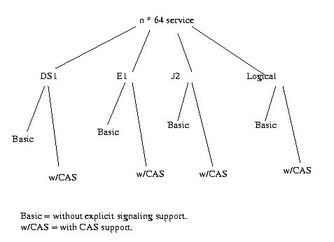
a) Service Description:
n*64 service is intended to emulate a point-to-point fractional DS1, E1, or J2 circuit. The service is accessed through either 1.544Mbps DSX-1 (T1.102) interfaces, 2048-Mbps (G.703) interfaces, or 6.312-Mbps (JT-G.703a) interfaces. For DS1, n of the 24 timeslots available at the DSX-1 interface, where n ranges from 1 to 24, are carried across the ATM network. Because the n*64 service can be configured to use only a fraction of the timeslots available on the service interface, it is possible to allow several independent emulated circuits to share one service interface as shown in the fig [figure no]. The capability of allowing several AAL1 entities to share one service interface, where each AAL entity is associated with a different virtual channel connection (VCC), allows for functional emulation of a DS1/DS0, E1/DS0, or J2/DS0 digital cross-connect switch. The ATM layer is responsible for multiplexing and demultiplexing several VCCs, one to each AAL 1 entity. Each AAL1 entity is responsible for performing segmentation and reassembly on one VCC.
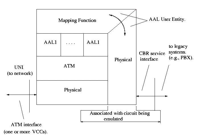
b) Framing And TimeSlot Assignment.
DS1 n*64 service can interface with the circuits using ESF (Extended Superframe Format), or Superframe Format (SF) framing format. The n*64 service will carry any group of n*64 -kbps timeslots, where n can be 1 to 24, 1 to 31, or 1 to 96 for DS1/E1 and J2, respectively. The timeslots assigned to a virtual channel are not required contiguous. The CES IWFs must deliver the output in the order it received.
c) Clocking
The DS1/E1/J2 n*64-kbps service requires the use of synchronous circuit timing, which is recommended by ITU I.363.1.
d) Jitter and Wander
Jitter measured at the IWF service interface must meet the standards of ANSI T1.403 and G.824 and the wander must meet ANSI T1.403 and G.824 for DS1 circuits. The ANSI T1.403 specifies that wander will not exceed 28 UI (18 microsec) peak to peak in any 24-hour period. G.823 and G.824 require that network wander be maintained less than 10 microsec over any 10,000-s interval.
e) Signaling Bits
The n*64 service can support signaling either with channel-associated signaling (CAS) or without CAS. With CAS requires direct recognition and manipulation of the signaling bits by the CES IWF.
f) AAL1 requirements
The n*64 service use the structured data transfer (SDT) mode as defined in I.363.1.
Unstructured service represents all modes of the unstructured DS1/E1 and J2 unstructured service [ Minoli98].
a) Service Description:
This service is intended to emulate a point-to-point DS1, E1, or J2 circuit. The service is accessed through either T1.102 interfaces, or G.703 interfaces. The service is defined as a clear channel pipe, transparently carrying any arbitrary 1.544-Mbps data stream.
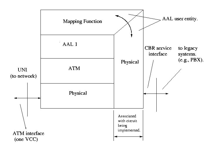
In reference to framing formats, most of the standards, like SF, ESF, G.704 are supported. This service has two modes for timing user equipment attached to the service interface, namely, synchronous mode and the asynchronous mode. The CES IWF has to implement atleast one of the two clocking modes. Jitter at the IWF service interface will meet ANSI T1.102 and G.824 for DS1 circuits, G.823 for E1 circuits with any clocking mode. If synchronous clocking or asynchronous clocking with SRTS clock recovery is used, wander must meet ANSI T1.403 and G.824 for DS1 circuits. This service will use the unstructured data transfer (UDT) mode as defined in T1.630 and I.363.1.
This represents all modes of the unstructured DS3/E3 service. This service is intended to emulate a point-to-point DS3 or D3 circuit. The service is accessed through either 44.736 Mbps DSX-3 interfaces or 34.368-Mbps G.703 interfaces. Framing formats other than standard DS3 or E3 formats cannot be supported.
ATM Virtual Channel Requirements
ATM network providing CES should also consider QoS parameters like Peak Cell Rate (PCR) and Cell Delay Variation (CDV). There are standards which specify what values is optimum for these parameters.
CES's advantages are the simplicity of implementation. The ATM network is used to provide virtual replacements for physical links in an existing network. Still, CES has two limitations. Firstly, it is unable to provide any statistical multiplexing. It does not differentiate between idle and active timeslots, which means all idle traffic is carried. Therefore, CES voice transport consumes 10% more bandwidth than would be required to transfer the same voice traffic over leased circuits. Secondly, it is often implemented as a point-to-point service - providing the transport of the contents of one network physical interface to another physical network interface. This can prevent the implementation of some network topologies, and can result in increased network cost.
The limitations in CES resulted in the development of a new standard from the VTOA workgroup of ATM Forum, af-vtoa-0085.000 [ af-vtoa-0085.000], in July 1997, which is also referred to as "Dynamic Bandwidth Circuit Emulation Services DB-CES".
The objective of this standard is to detect active or inactive timeslots of a legacy TDM trunk from a PBX or multiplexer and dropping that timeslot from the next ATM structure. This enables to use this bandwidth to be reutilized for other services like CBR, VBR, UBR, ABR applications.
To meet the specification of DBCES, it is necessary to detect the idle timeslots. There are atpresent two techniques by which idle timeslots can be detected.
a) Idle detection utilizing idle code pattern
The idle status of a timeslot can be detected at the transmitting IWF by detecting the continuous occurrence of an idle code pattern in that timeslot's data for some specified time interval.
b) Idle detection using AB signaling bits in CAS
With CAS, the value of the AB bits used to determine the idle status of the timeslots on a given connection should be user configurable, which allows the IWF's user to configure the values on the basis of the supported terminal equipment and match the values on the two sides of the virtual connection.
Figure below shows the reference model for DB-CES [ Minoli98].

ATM device shown may be a physical or a functional entity that provides several interfaces to users as well as to other network elements. The CES InterWorking Function (CES IWF), included in this device is responsible for the following functions:
"ATM queue with DBU" represents the queue that is responsible for queueing and transmitting the cells from the different interfaces onto a single common ATM interface. The DBU (Dynamic Bandwidth Unit) assigns a fixed bandwidth (cell rate) to each of the CES interworking functions, which corresponds to the maximum structure size expected to be handled. When all the timeslots in a given CES IWF are active, this entire bandwidth is needed for serving that CES IWF. When some of the CES IWF's timeslots are not active, the IWF dynamically reduces the size of the structure thereby transmitting a lower cell rate to the ATM queue. The DBU capability in the queue can then temporarily assign the bandwidth not used by its "owner" IWF to another service. This capability would provide bandwidth for UBR-type services without having to reserve MCR (Minimum Cell Rate)/PCR (Peak Cell Rate), thus increasing the effective bandwidth utilization on the ATM interfaces.
To still illustrate the key concepts of the specification, it is appropriate to define the following terms:
a) Dynamic Structure Sizing (DSS): It is the ability of a CES IWF to dynamically adjust the size of the AAL 1 structure based on the number of active timeslots contained in the DS1/E1 trunk undergoing circuit emulation. This structure also has a maximum size limit, which is set at the time of configuring the IWF.
b) Configured Structure: It is the maximum size AAL1 structure when all assigned timeslots of a given trunk are active. This is predetermined by the maximum number n of the 64-kbps timeslots provisioned on the trunk at the time of configuring the IWF.
c) Active Structure: It is the AAL1 structure containing the information from actually active timeslots at any given instance. Inactive timeslots are not mapped into the AAL1 structure. There are two types of active structure.
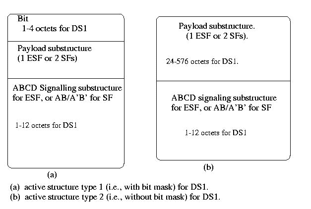
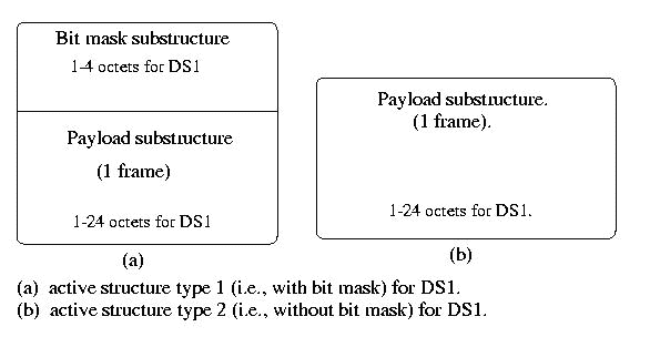
The bit mask is usually transmitted only in structures containing a pointer ( with the exception being when transitioning from all inactive slots to atleast one active slot, in which case there may be one structure with a bit mask that does not have a pointer). This way, we can minimize the bandwidth usage and provide deterministic location of the bit mask after the pointer.
d) Bit mask: It is a bit pattern that indicates the activity status of the assigned n timeslots. This bit pattern is always created by the ATM transmitter and enclosed in the AAL1 structure to enable the ATM receiver to correctly place the retrieved timeslots in the DS1/E1 frame that it reconstructs.
e) Inactive Structure: It is a structure one to four octets long transmitted when all the timeslots are inactive. It contains only a bit mask full of zeros, with a parity bit of value 1, and no payload or signaling substructure.
3.2.2 Procedures
Each IWF is configured by assigning specific timeslots corresponding to each virtual connection in each direction of transmission. In addition, the following parameters must be configured for each timeslot for proper operations:
In full-duplex connections, both directions contain the same number of assigned timeslots (n*64), but generally different timeslot positions in the DS1/E1 frame. The following procedures address one direction of transmission.
The transmitting IWF (transmitter) determines each timeslot's activity status from the information received from both the local and remote DS1/E1 equipment in the signaling bits related to this timeslot. The transmitter then format the TDM active timeslots into one of the two AAL1 structure types. At the beginning from the quiescent state, or whenever the number of active timeslots changes, an active structure with bit mask will be transmitted at the next available opportunity. This is required to assure proper structure alignment in the receiver.
The receiving IWD (receiver) will calculate the length of the payload/signaling substructure from the value of the bit mask that is located at the beginning of the payload of active structure type 1. The calculated length will be used as the length of all subsequent type 2 structures, until the next bit mask is received. The new bit mask might either verify or change the calculated length.
The foregoing CES mechanisms treat voice as being a constant stream of information encoded as a CBR stream. But in the real sense, voice is a combination of talk spurt and silence. So, it is waste on bandwidth in transmitting the silence. Also, these mechanisms typically minimise the problems of cell construction delay by transmitting the voice as an uncompressed 64kbps. Such approaches deny the network operator by gaining significant bandwidth from voice compression technologies.
To address these limitations, ATM Forum came up with the advanced mechanism for the transport of voice as a variable bit rate (VBR) compressed stream. This mechanism is described in the specification, af-vtoa-0113.000 [ af-vtoa-0113.000], referred as "ATM Trunking using AAL2 for Narrowband Services".
Before getting into the details of the specification, here is a brief introduction on AAL2.
AAL2 is a new ATM Adaptation Layer, specified in ITU-T Recommendation I.363.2 (1997) with the specific mandate to provide efficient Voice-Over-ATM services. AAL2 supports, in addition to that of AAL1, the following features:
The structure of AAL2, as defined in ITU-T Recommendation I.363.2, is shown in the fig. [ GDC99a].
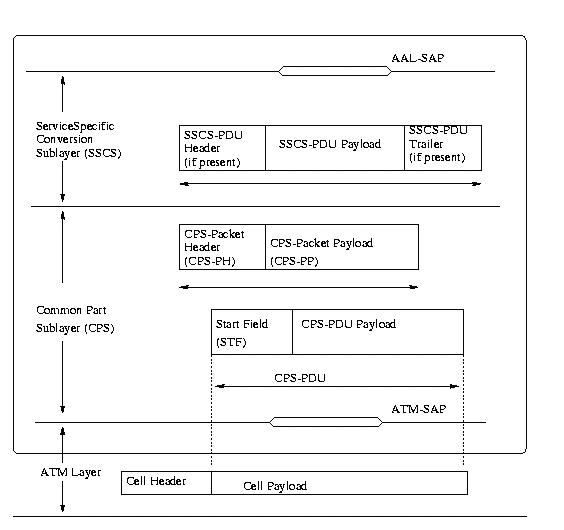
AAL2 is divided into two sub-layers: the Common Part Sub-layer (CPS) and the Service Specific Convergence Sub-layer (SSCS).
a) AAL2 Common Part Sub-layer (CPS)
CPS provides the basic structure for identifying the users of the AAL, assembling/disassembling the variable payload associated with each individual user, error correction, and the relationship with the SSCS. Each AAL2 user can select a given AAL-SAP associated with the QoS required to transport that individual higher layer application. AAL2 makes use of the service provided by the underlying ATM layer. Multiple AAL connections can be associated with a single ATM layer connection, allowing multiplexing at the AAL layer.
b) AAL2 Service Specific Convergence Sub-Layer (SSCS)
According to the recommendations of the ITU-T I.363.2, the SSCS is defined as the link between the AAL2 CPS and the higher layer applications of the individual AAL2 users. Several SSCS definitions that take advantage of the AAL2 structure for various higher layer applications are planned. A null SSCS, already understood and used in conjunction with the AAL2 CPS, satisfies most mobile voice applications. To satisfy higher layer requirements associated with data and AAL2 configuration messages - called AAL2 Negotiation Procedures, or ANP - an SSCS for segmentation/reassembly (temporarily called I.SEG) is in development within the ITU-T Study Group 13.
The above section gave the overview for understanding for AAL-2. This would be helpful in comprehending the ATM Trunking standard, which we are going to discuss below.
The reference model for this standard is shown in the figure below.
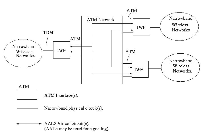
The figure shows how the ATM network is connected to narrowband networks with the help of InterWorking functions. In the above figure, The IWFs provide capabilities that are categorized as switched or non-switched trunking.
a) Switched Trunking
Switched trunking involves analysis of the signaling that accompanies an incoming narrowband call and routing of its bearer information to an AAL2 channel within a VCC between IWFs. Once the narrowband call has ended, subsequent calls occupying the same narrowband channel (TDM timeslot) may be switched to different AAL2 channels and VCCs. In other words, there is no permanent relationship between a narrowband channel and an AAL2 channel.
b) Non-Switched Trunking
In non-switched trunking, the information stream of a narrowband channel is always carried on the same AAL2 channel within the same VCC and vice-versa. In other words, there is a permanent correspondence between a narrowband channel and the AAL2 channel and VCC designated for its support. Non-switched trunking involves no termination of signaling and no routing of narrowband calls in the IWFs.
IWF complying with this standard might support silence removal, i.e., suppression of the transfer of AAL2 packets during silent intervals and insertion of the appropriate background noise at the distant end. IWF might also support conversion between 64kbps PCM (from the narrowband side and any of the supported encoding on the ATM side. IWF might also provide special capabilities to transport voice band data through modem detection, fax data through demodulation and remodulation, DTMF information through DTMF packets.
Figure below depicts the manner in which the services listed above are supported by the various portions of the ATM protocol architecture.
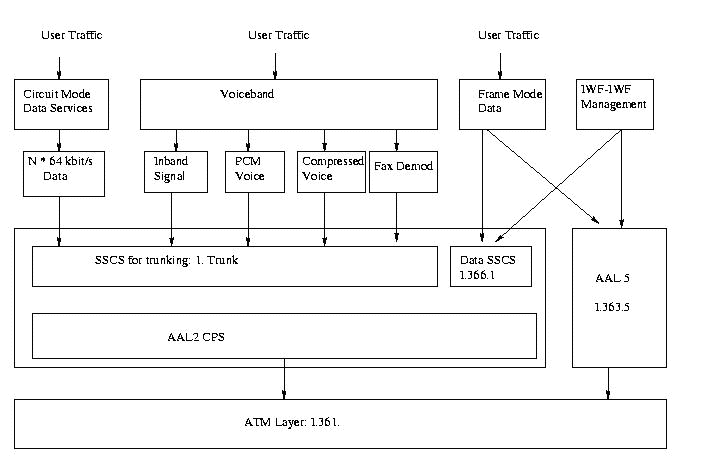
A major benefit of ATM trunking using AAL2 for narrowband services is bandwidth savings. It can be achieved in these ways.
| Standards | Voice
Compression |
Silence
Removal |
Idle Channel
Suppression. |
Switched
Concentration. |
| CES | No | No. | No. | No. |
| DB-CES | No. | No. | Yes. | No. |
| ATM Trunking using
AAL2 for Narrowband services |
Yes. | Yes. | Yes. | Yes. |
As a testimony of the viability of VTOA technology, many vendors have started supporting VTOA in their switches. Since initially there was no any standard, most of the vendors' implementations are proprietary and incompatible with each other. Many smaller equipment vendors already have products that can be used as components to implement a VTOA network.
Here are some of the companies doing some pioneering research to bring up new VTOA products.
GDC claims that its product Voice Service Module (VSM) is the industry's first standards-based Voice Over ATM product. VSM delivers the first product in the industry to offer both standard-based variable-bit-rate (VBR) and constant-bit-rate (CBR) voice solutions on a single hardware platform that is fully integrated across the industry's leading family of access multiplexers and edge switches. The VSM is compliant with the recently determined ITU-T I.363.2 Recommendation. It can also be deployed in a Structured Circuit Emulation Mode as defined in the ATM Forum's CES-IS document (af-vtoa-0078.000).
VoicePlus delivers robust Circuit Emulation Service for the seamless migration of time division multiplexing (TDM) equipment to a common multi-service ATM infrastructure. VoicePlus enables FORE's customers to optimize their investment in ATM switching by taking full advantage of ATM's inherent quality-of-service (QoS) capabilities, cost-effectively consolidating separate overlay voice, videoconferencing, video distribution, and data networks to a scalable ATM backbone. Substantial network savings are realized through the reduction of leased line charges, network support and administrative costs, and overall network complexity. The VoicePlus network module is fully compatible with FORE's existing line of ASX-200BX, ASX-1000, and ASX-1200 backbone ATM switches
The Cisco 3800 family of multiservice, integrated access platforms enables organizations to integrate all traffic---legacy data, LAN traffic, voice, fax, and video---over a single network backbone. The Cisco 3800 can be deployed over private or public networks, dramatically reducing equipment and connection costs, simplifying network management, and improving application performance. The Cisco 3800 combines switched voice, LAN traffic, and legacy data over Frame Relay or leased lines at speeds up to T1/E1. The 3800 is based on IOS and is also tightly integrated with the Cisco IGX.
For integrated voice and data applications, the Catalyst 8500 family supports multiservice integration over IP or ATM by combining T1/E1 interfaces to Private Branch Exchanges (PBX) and the public voice network with advanced call processing control software from Cisco. For networks requiring only Layer 3 capabilities, the Catalyst 8500 platforms have cost-optimized configuration options.
Back to Table of ContentsFrom the foregoing discussions, one can deduce that ATM holds a promising future in integrating voice and data onto a single network. We found that to transmit voice over a network, various technical challenges, like QoS, signaling, and synchronization, have to be addressed.. Standards got evolved in later 1990s from the VTOA workgroup of ATM Forum, which addressed these challenges. A standard on Circuit Emulation Services (CES) was defined in earlier 1997, which contained specifications for supporting voice as a CBR kind of traffic. The specification allowed user to establish an AAL1 connection to support a T1/E1 circuit over the ATM backbone.. Later, to exploit the advantages of voice traffic, Dynamic Bandwidth CES was defined in July 1997. Here, idle timeslots in the TDM trunk was detected and was not transmitted over the network. Thus the bandwidth got saved and efficiently utilized for other ATM services. In both these specifications, voice was treated as CBR traffic although it was a VBR kind of traffic, with a combination of talk spurt and silence. New adaptation layer, AAL2 was then designed by ITU-T, aimed at transmitting voice as VBR traffic and providing better quality of service. ATM Forum then came up with a standard in February 1999, "ATM Trunking using AAL2 for narrowband services", which took advantages of the features provided by AAL2 for transmitting voice.
Towards the end of the paper, we had a brief overview on various products that are in the market supporting voice over ATM networks. Some of these products were developed based on proprietary standards and some were developed based on the ATM Forum's standards.
Since the standards are taking time to establish itself, it takes time for most of the vendors to develop products based on these ATM Forum's standards. Once this is done, network administrators and service providers can contemplate on investing on these products to setup ATM networks for providing voice traffic, so that they can achieve major savings in bandwidth and network complexity and reap greater success in terms of reliability and costs. So, by next millennium we can imagine the world of voice being taken over by ATM!!
Back to Table of Contents
[af-vtoa-0078.000] ATM Forum, "Circuit Emulation Service Interoperability Specification Version 2.0", January 1997, 94 pages,
ftp://ftp.atmforum.com/pub/approved-specs/af-vtoa-0078.000.pdf
This discusses the specification of Circuit Emulation Services from ATM
[af-vtoa-0085.000] ATM Forum, "Specifications of (DBCES) Dynamic Bandwidth Utilization - In 64Kbps Time Slot Trunking Over ATM - Using CES" July 1997, 36 pages,
ftp://ftp.atmforum.com/pub/approved-specs/af-vtoa-0085.000.pdf
This comprehensively discusses the dynamic allocation of bandwidth for Circuit Emulation Services
[af-vtoa-0113.000] ATM Forum, "ATM Trunking using AAL2 for Narrowband Services", February 1999, 52 pages,
ftp://ftp.atmforum.com/pub/approved-specs/af-vtoa-0113.000.pdf
This discusses how AAL2 services can be used to transmit voice efficiently
[ATMContr98] Choi, DoD; Pierce DoD, "Further Comments on Straw Ballot for ATM Trunking using AAL2 for Narrowband services", ATM_Forum/98-0886, August 1998, 1 page.
This contains the comments made on the contributions from the members of the ATM Forum on ATM Trunking using AAL2.
[ATMForum99] ATM Forum, "Speaking Clearly with ATM - A practical guide to carrying voice over ATM", September 99,
http://www.atmforum.com/atmforum/library/practical_voiceover.html
White paper from ATMForum which details the latest in VTOA. Good paper to know the latest in VTOA
[Jain97] Jayaraman Iyer, Raj Jain, Sohail Munir, Sudhir Dixit, "Performance of Compressed Voice Sources over VBR", ATM Forum/97-0608, July 1997, 11 pages,
http://www.cse.wustl.edu/~jain/atmf/atm97-0608.htmThis is an article concentrating on analyzing the performance of voice traffic over VBR service
[NewBridge98] New Bridge, "Integrating Voice Services onto ATM: Engineering Considerations", October 1998, 11 pages,
http://prodweb.newbridge.com:80/resources/whitepapers/voatm_wp_sum.jhtml.
White paper from NewBridge, which discusses some of the technical challenges in implementing ATM networks supporting voice.
[Fore99a] Fore Systems, "Voice-Over-ATM: Ringing in LAN Telephony", September 1997,
http://www.fore.com/products/wp/voicewp.htm
White paper that discusses on incorporating VTOA over LAN
[GDC99a] General DataComm, "A Management Briefing on Adapting Voice For ATM Networks: An AAL2 Tutorial", 12 pages,
http://www.gdc.com/inotes/pdf/aal2tut.pdf
This is a very good tutorial to get to know about AAL2 and how AAL2
service supports VTOA
[GDC99b] General DataComm, "A Management Briefing on Adapting Voice For ATM Networks: A Comparison of AAL1 Versus AAL2", 10 pages,
http://www.gdc.com/inotes/pdf/aal1vs2.pdf
This is a very good article to get to know about AAL2 and how AAL2 service supports VTOA. This also highlights the difference between AAL1 and AAL2
[Minoli98] Daniel Minoli, Emma Minoli, "Delivering Voice over Frame Relay and ATM", John Wiley & Sons, 1998, 460 pages.
The only book that is available as of now on Voice Over ATM. This explains clearly all the standards that are specified by ATM Forum.
[Cisco99a] Cisco, "Cisco 3800", 3 pages
http://www.cisco.com/warp/public/cc/cisco/mkt/access/c3800/index.shtml
Product Description web site for Catalyst 3800
[Cisco99b] Cisco, "Catalyst 8500", 2 pages
http://www.cisco.com/warp/public/cc/cisco/mkt/switch/cat/8500/index.shtml.
Product Description web site for Catalyst 8500
[Fore99] Fore Systems, "Voice Plus", 2 pages
http://www.fore.com/products/voice-plus/voice-plus_po.html
Product Description web site for Voice Plus
[GDC99] General Data Comm, "GDC APEX Voice Service Module",
http://www.alliancedatacom.com/gdc-apex-vsm.htm
| AAL | - | ATM Adaptation Layer. |
| ADPCM | - | Adaptive Differential Pulse Code Modulation. |
| CAS | - | Channel Associated Signaling. |
| CCS | - | Common Channel Signaling. |
| CDV | - | Cell Delay Variation. |
| CES | - | Circuit Emulation Service. |
| CELP | - | Code Excited Linear Prediction. |
| DB-CES | - | Dynamic Bandwidth Circuit Emulation Service. |
| LD-CELP | - | Low Delay Code Excited Linear Prediction. |
| PCM | - | Pulse Code Modulation. |
| PSTN | - | Public Switched Telephone Network. |
| QoS | - | Quality of Service. |
| SRTS | - | Synchronous Residual Time Stamping. |
| VCC | - | Virtual Circuit Channel. |
| VTOA | - | Voice and Telephony Over ATM. |