First and second generation wireless networks currently provide support for circuit-switched voice services as well as low-rate circuit-switched and packet-switched data services. The most widely deployed first generation analog mobile phone systems are Advanced Mobile Phone System (AMPS), Nordic Mobile Telephone (NMT), and Total Access Communications System (TACS). AMPS has major network deployments in North America, the Asia/Pacific region, and Central and Latin America. NMT and TACS first deployments were primarily in Europe – NMT in Scandanavia and TACS in the United Kingdom, with other substantial network operations in the Asia/Pacific region.
Second generation (2G) systems consist of Global System for Mobile Communications (GSM), IS-136 or Digital AMPS (DAMPS), IS-95 or cdmaOne™, and Personal Digital Cellular (PDC). GSM, IS-136, and PDC are time-division multiple access (TDMA) based systems; whereas, IS-95 relies on code division multiple access (CDMA) as its air interface. GSM is widely deployed throughout the world and is the predominant standard in Europe. GSM is also recognized as the world leader in terms of number of subscribers. IS-136 and IS-95 are the main 2G standards in operation in the North America, with other major installations throughout Central and South America and the Asia/Pacific region. Although it supports the second largest digital subscriber base, PDC is currently only in operation in Japan. Table 1 shows the estimated number of subscribers by technology as of mid-year 1999.
| GSM | PDC | IS-95 | IS-136 | |
| Subscribers (Millions) | 183 | 42 | 32 | 24 |
The primary focus of third generation (henceforth referred to as 3G) architectures will be to attempt to seamlessly evolve second generation systems to provide high-speed data services to support multimedia applications such as web browsing. The key word is "evolve" - as the challenge to wireless equipment manufacturers is to provide existing customers, namely, service providers, with a migration path that simultaneously satisfies the requirements set forth by the International Telecommunications Union (ITU) for 3G wireless services while preserving customer investment in existing wireless infrastructure.
International Mobile Telecommunications in the year 2000 (IMT-2000) is the 3G specification under development by the ITU that will provide enhanced voice, data, and multimedia services over wireless networks. In its current state, the plan is for IMT-2000 to specify a "family of standards" that will provide at least 384 kbps data rate at pedestrian speeds, 144 kbps at mobile speeds, and up to 2 Mbps in an indoor environment. Universal Mobile Telecommunications System (UMTS) is often used synonymously with IMT-2000; however, UMTS is also frequently used in context with a specific air interface proposal known as wideband CDMA (see below).
Numerous standards bodies throughout the world have submitted proposals to the ITU on UMTS/IMT-2000. In 1997 Japan’s major standards body, the Association for Radio Industry and Business (ARIB), became the driving force behind a third-generation radio transmission technology known as wideband CDMA (WCDMA). In Europe, the European Telecommunications Standards Institute (ETSI) Special Mobile Group (SMG) technical subcommittee has overall responsibility for UMTS standardization. ETSI and ARIB have managed to merge their technical proposal into one harmonized WCDMA standard air interface. In the United States, the Telecommunications Industry Association (TIA) has proposed two air interface standards for IMT-2000, one based on CDMA and the other based on TDMA. Technical committee TR45.5 within TIA proposed a CDMA-based air interface, referred to as cdma2000, that maintains backward compatibility with existing IS-95 networks. The second proposal comes from TR45.3, which adopted the Universal Wireless Communications Consortium’s (UWCC) recommendation for a third-generation air interface that builds off of existing IS-136 networks. Last but not least, the South Korean Telecommunications Technology Association (TTA) supports two air interface proposals, one similar to WCDMA and the other to cdma2000.
In the discussion that follows, key enhancements that will allow GSM, IS-136, and IS-95 networks to meet IMT-2000 requirements will be described. Section 2 describes the evolution of GSM networks, and section 3 describes planned enhancements to the IS-136 network architecture. Section 4 describes cdma2000 enhancements, and the summary provides a brief overview of the latest 3G standards developments.
GSM networks will enhance packet data services primarily in three phases. General Packet Radio Services (GPRS) refers to the first phase of GSM network architecture enhancements that allow mobiles to connect to IP or X.25 based networks. The GSM/GPRS network architecture will further evolve to support Enhanced Data Rates for GSM Evolution (EDGE), which provides significant improvements over GPRS. Finally, the ETSI/ARIB Wideband CDMA (WCDMA) proposal provides a new air interface for GSM networks - supporting higher data rates that will meet or exceed UMTS/IMT-2000 specifications.
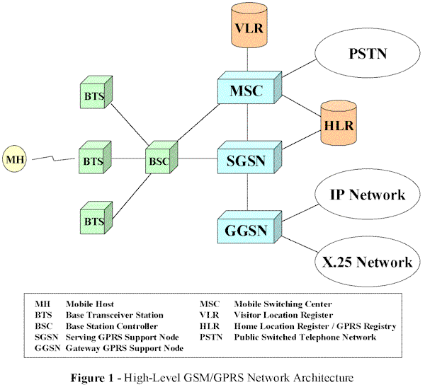
GPRS allows GSM mobile subscribers to connect to an IP-based or X.25-based network. Two new network elements are introduced with GPRS to the GSM architecture (see Figure 1): the serving GPRS support node (SGSN) and the gateway GPRS support node (GGSN). The SGSN provides authentication and mobility management. To maintain as much commonality as possible with existing GSM networks, the GPRS mobility management protocols are derived from GSM Mobile Application Protocol (MAP). At a high level, the SGSN provides similar functionality to the packet data network that the MSC/VLR provides to the circuit-switched network. The GGSN provides the interface between the mobile and the IP or X.25 network. The GGSN tunnels packets from the packet data network using the GPRS tunneling protocol. When a mobile wants to send data, it must set up what is referred to as a packet data protocol (PDP) context between the SGSN and the GGSN, which is more or less equivalent (at least in the context of IP) to obtaining an IP address. After setting up a PDP context, the mobile can then begin using GPRS point-to-point or point-to-multipoint services.

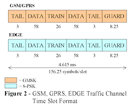
GPRS cells may dedicate or share one or more physical channels, called packet data channels (PDCH), for packet-switched services within the cell. The time slot structure for GPRS is the same as in GSM (see Figure 2). GPRS defines a new burst mode of operation for packet data transfer in which bursts consist of 456 bits of coded information interleaved across the equivalent of four time slots (i.e., 4 slots with 114 bits each). GPRS uses the same 1-bit per symbol modulation scheme used in GSM - Gaussian minimum shift keying (GMSK). In addition, GPRS defines four different levels of coding, CS-1 through CS-4, each capable of obtaining higher data rates than its predecessor. Table 2 summarizes these coding schemes. The USF, data, parity, and tail bits are concatenated, convolutionally encoded at the given rate, and then punctured accordingly to yield the desired 456 bits. Note that for CS-4 no convolutional encoding is done.
The PDCH consists of three logical channels. GPRS bursts are carried over the logical packet data traffic channel (PDTCH). In addition to the logical PDTCH, GPRS defines a logical packet broadcast control channel (PBCCH) as well as a packet common control channel (PCCCH). The PBCCH is used to convey system information to the mobile. The PCCCH serves multiple functions. On this channel, a mobile listens or "camps" awaiting the arrival of signaling messages – for example, a paging message indicating the start of a packet transfer. Not all cells will necessarily have a PCCCH. In this instance, a mobile will listen to the standard GSM common control channel instead. A mobile also uses the PCCCH to respond to a paging message as well as signal the base station when it wishes to initiate a packet transfer. Finally, the PCCCH is also used by the base station to indicate uplink resource allocations that have been made to a particular mobile for packet data transfer. The reservations are ultimately transferred on the PDCH using the uplink status flag (USF) field (see Table 2).
| Coding Scheme | USF Bits | Data Bits | Parity Bits | Tail Bits | Coding Rate | Punctured Bits | Total Bits |
| CS-1 | 3 | 181 | 40 | 4 | 1/2 | 0 | 456 |
| CS-2 | 6 | 268 | 16 | 4 | 1/2 | 132 | 456 |
| CS-3 | 6 | 312 | 16 | 4 | 1/2 | 220 | 456 |
| CS-4 | 12 | 428 | 16 | 0 | 1 | 0 | 456 |
GPRS also defines three classes of terminals: class A, class B, and class C. A class A terminal supports simultaneous circuit-switched and packet-switched traffic. A class B terminal can be attached to the network as both a circuit-switched and packet-switched client but can only support traffic from one service at a time. Finally, a class C terminal uses only packet-switched services.
EDGE has been approved by ETSI as well as adopted by the UWCC as the outdoor component of 136HS (see IS-136 Evolution below). Standards work is currently underway in ETSI so as to realize this new radio access technology in existing GSM networks. As does GPRS, EDGE will use the 200 kHz carrier and multi-slot operation, which will allow service providers to deploy EDGE transceivers among existing GSM/GPRS transceivers. In addition, EDGE reuses the GSM/GPRS time slot structure (Figure 2). One of the main differences between GPRS and EDGE is that EDGE will use 8-phase shift keying (8-PSK) modulation, which encodes 3 bits per modulated symbol, as opposed to the 1-bit per symbol GMSK used in existing GSM and GPRS networks.
EDGE will also provide higher data rates than currently possible in GPRS by taking advantage of channel quality above and beyond the minimum requirements. The key concept is the following: for voice, if the signal-to-interference ratio (SIR) drops below the minimum requirements, the voice call is dropped; conversely, as the channel quality increases above and beyond the minimum required SIR, there exists little incremental benefit to the user. Said another way, a voice call only gets so good. With EDGE, an adaptive radio link protocol will be employed to take advantage of the better channel quality. As channel quality increases, both higher level modulation techniques as well as decreased coding (i.e., less protection for the data) will be used to obtain higher data rates.
Currently, a mode-switching adaptive modulation technique has been proposed. The mode-switching proposal encodes data over 4 time slots using 1 of 6 coding levels, depending on channel conditions. Also under consideration is an adaptive radio link protocol using incremental redundancy – similar to the one planned for IS-136+ packet data service enhancements (see below). Incremental redundancy is a technique by which data is encoded only on an "as needed" basis. If the decoding of a block fails at the receiver, then the next block is transmitted using an increased level of protection to further guard against errors on a channel that is assumed to be deteriorating. The advantages of an incremental redundancy scheme compared to mode-switching in terms of both throughput and delay have been demonstrated in [ VanNobelen99]. In addition, the complexities of actually realizing a mode-switching protocol are also discussed in [ VanNobelen99].
Finally, with respect to mobile terminals, two classes are being considered. The first class would only support 8-PSK on the downlink and GMSK on the uplink, thereby only allowing higher data rates on the forward channel. The benefits are a lower cost handset without necessarily a substantial performance penalty; that is, most applications (e.g., web browsing) are expected to only require that higher data rates be realized on the downlink. The second class of terminal would support 8-PSK on both the forward and reverse channels.
WCDMA introduces a new air interface based on a 5 MHz channel bandwidth. The original WCDMA proposal called for a 4.096 Mcps chip rate; however, recently agreements have been made to compromise on a lower rate of 3.84 Mcps to allow for easier implementation of terminals that support both WCDMA and cdma2000 (see below). WCDMA will also utilize a 10 ms 16 slot/frame structure and perform closed power control on both the forward and reverse link at a rate of 1,600 times per second. Another important aspect of WCDMA is that is specifies asynchronous base station operation, unlike its cdma2000 counterpart. Asynchronous base station operation eliminates the need for base stations to communicate with the Global Positioning System (GPS) and may allow for easier installation/integration of indoor WCDMA deployments with outdoor infrastructure. Finally, WCDMA will employ variable-length orthogonal spreading sequences for channel separation on both the forward and reverse links.
The WCDMA physical layer will provide two types of packet access on either the random access channel or a dedicated (user) channel. Random access is used only on the uplink for short infrequent bursts. A random access burst may carry both control and/or data from the mobile to the base station. Dedicated access is provided by a dedicated channel for longer more frequent bursts on both the uplink and downlink. The random access method is advantageous for shorter infrequent bursts as the channel is not maintained between bursts, thereby resulting in less overhead.
The WCDMA physical layer also offers the following control transport channels: broadcast control channel, paging channel, and forward access channel. The broadcast channel will be used to convey system control information on the downlink, and the paging and forward access channels are used to carry control information to the mobile. Among other types of control information, the forward access channel will be used to acknowledge bursts on the random access channel.
IS-136, sometimes referred to as North American TDMA (NA-TDMA), has a two phase migration path as defined by UWC-136. In the first phase, referred to as 136+, significant enhancement will be made to allow for improved voice and data over the existing 30 kHz carrier, which uses 6 time slots per 40 millisecond frame. The second phase, referred to as 136 High Speed (136HS), will embrace the EDGE standard (at least in outdoor environments) in order to meet the requirements of UMTS/IMT-2000.
IS-136+ significantly improves both the voice and data services available using the existing 30 kHz channel bandwidth. Enhancements for improved voice services employ the use of more efficient channel coding schemes, higher bit per symbol modulation schemes, as well as improved vocoders. IS-136+ introduces a second channel coding scheme, referred to as Channel Coding 2 (CC2) to improve voice quality on the downlink (base station to mobile) digital traffic channel (DTCH). As does its predecessor, Channel Coding 1 (CC1), CC2 uses p /4-differential quadrature phase shift keying ( p /4-DQPSK), which encodes 2 bits per symbol, at a symbol rate of 24.3 kHz. Hence, one can encode 324 bits in every 6.67 ms time slot. This corresponds to a bit rate of 16.2 kbps for a full-rate channel (i.e., 2 slots per 40 ms frame). CC2’s advantage lies in enhancing the downlink time slot structure by allowing additional bits to be used to encode voice traffic as well as including fast power control. A comparison of the original CC1 and CC2 is given in Figure 3. CC2 eliminates the 12-bit slow-associated control channel (SACCH) as well as the 11-bit digital control channel locator (DL) field. In their place, CC2 substitutes 18 additional data bits, 1 fast power control bit (F), and a 4-bit power control ramp field (PRAMP). Downlink power control will be used on the DTCH, but not on the digital control channel (DCCH). Although uplink power control will aid in reducing adjacent slot interference, the base station will employ the fast power control if and only if all mobiles on the DTCH are 136+ capable.
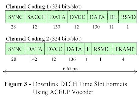
136+ voice quality will also benefit from the use of more advanced vocoders. As of 1997, the algebraic code excited linear predictive (ACELP) vocoder replaced the original IS-136 vector sum excitation linear predictive (VSELP) vocoder. The ACELP vocoder outputs three classes of speech: class 1a, class 1b, and class 2. For each CC2 time slot, the ACELP vocoder generates 48 class 1a bits, 48 class 1b bits, and 52 class 2 bits.. Class 1a bits are considered to be the most audibly significant bits and are encoded using a 7-bit CRC, 1/3 convolutional encoding, and 28-bit puncturing for a total of 137 bits. Class 1b bits are encoded at a rate of 1/2 with 7 bits removed for a total of 89 bits. Finally, the 55 class 2 bits, considered the least important, are not encoded, thus filling the 278-bit data portion of a CC2 time slot. The 278 bits are then interleaved within the block, and the block is interleaved across multiple time slots to guard against burst errors.
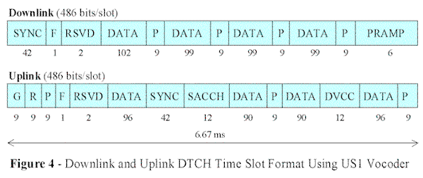
IS-136+ also defines another voice service using the US1 vocoder, which is based on the GSM Enhanced Full Rate (EFR) vocoder. The US1 vocoder uses 8-PSK modulation (3 bits per modulated symbol) at a rate of 24.3 kHz. This allows for data rates of 24.3 kbps on a full-rate DTCH, or equivalently, 486 bits per time slot. Figure 4 shows the uplink and downlink time slot structure using the US1 vocoder. Like the ACELP vocoder, the US1 vocoder also distinguishes between class 1a, class 1b, and class 2 speech. Details of the encoding used for the different classes can be found in [ Austin99]. Ultimately, a total of 399 and 372 data bits are encoded on the downlink and uplink respectively. Also, both the downlink and uplink time slot structures divide the data among so-called "pilot" fields (P), which allow for coherent detection at the receivers. As in CC2, the class 1a, 1b, and 2 bits are interleaved within the block, and the block is interleaved across multiple time slots to counteract the effects of fading.
Enhanced IS-136 packet data services is synonymous with GPRS-136; that is, IS-136+ enhanced packet data services will be based on the GPRS architecture (see GSM Evolution). However, because GPRS is derived from GSM MAP, the GPRS-136 network model will incorporate a GPRS Home Location Register (HLR) (see Figure 5). Mobility management will have to be carried out in parallel in order to avoid the complexity of attempting to merge GSM MAP and IS-41 signaling. Also, signaling information between the base station (BS) and mobile switching center (MSC) in the GPRS-136 architecture will be encapsulated and tunneled through the SGSN.
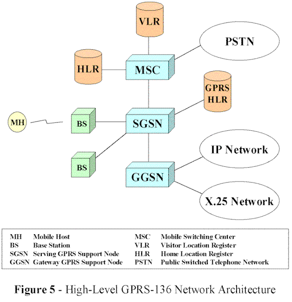
To implement GPRS-136, a new physical packet data channel (PDCH) is defined – just as in the GSM/GPRS architecture. During operation, the mobile continually listens to the PDCH or so-called "camps" on the PDCH. The PDCH consists of two logical channels on the uplink: a random access channel and a logical payload channel. On the downlink, the packet data channel consists of four logical channels: broadcast, paging, payload, and feedback. The broadcast channel is used for conveying system information, and the paging channel is used for tunneling IS-41 signaling messages to the mobile over the PDCH. For example, delivery of an IS-41 paging message over the paging channel would cause the mobile to switch to a DCCH. The downlink payload channel is self-explanatory, and the packet channel feedback (PCF) is used to acknowledge previously sent packets as well as allocate additional slots to a particular mobile on the uplink.
The uplink and downlink PDCH time slot formats are illustrated in Figures 6 and 7. In addition, [ Balachandran99] discusses an abbreviated uplink slot structure used for large cells. The PCF field occupies 24 bits in one downlink time slot. The first 12 bits are used to either acknowledge (ACK) or negatively acknowledge (NACK) the data sent in the previous uplink slot. The last 12 bits are used for reservation of the uplink. The PCF can either indicate that the next available slot is reserved for a given user (by providing a temporary identifier assigned to a mobile user in these 12 bits) or indicate that the slot is not reserved, thereby indicating that a mobile may attempt a random access on the PDCH.
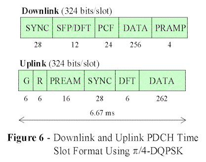
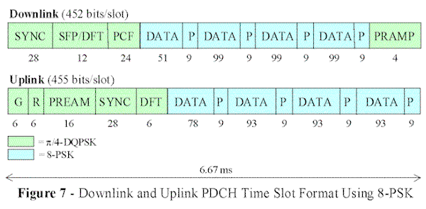
Another key enhancement used to provide higher data rates over the PDCH is the use of adaptive modulation. Depending on channel conditions, the datawithin a given time slot will be encoded using either p /4-DQPSK or 8-PSK, as indicated in Figures 6 and 7. When 8-PSK is used (Figure 7), pilot fields (P) are once again included in the data to allow for coherent detection at the receiver. Also, note that not all fields are encoded using 8-PSK; some fields, such as SYNC, are still modulated using p /4-DQPSK, presumably to allow for backward compatibility with handsets that only support this modulation scheme. In addition, allowances have been made to incorporate both fixed coding and incremental redundancy schemes with both types of modulation – where 8-PSK used in conjunction with incremental redundancy achieves the highest data rates since more bits are encoded per modulated symbol and redundant bits are only transmitted on an as needed basis.
Finally, other planned enhancements to the IS-136 network architecture include improved mobile-assisted handoffs, improved mobile-assisted channel allocation, and the use of smart antenna technology (see [ Austin99] and [ Sollenberger99] for more details).
The UWCC has adopted the EDGE standard (see GSM Evolution) for the outdoor component of IS-136HS. The main difference between EDGE deployments in existing IS-136 networks and GSM networks will be spectrum allocation. Because EDGE was originally designed to be compatible with GSM and conforms to the 200 kHz channel bandwidth 8-slot per frame structure, GSM operators will benefit from being able to mix both GSM transceivers and EDGE transceivers in the same bandwidth. For IS-136 operators, the consensus appears to be that EDGE technology will only be deployed within a limited 1MHz of spectrum. Said another way, bandwidth will be partitioned into 200 kHz EDGE channels and existing 30 kHz channels. In order to meet capacity requirements within the limited bandwidth allocation, a 1/3 re-use ratio has been proposed for EDGE carriers using fractional-loading. Fractional loading implies that not all time slots for a given EDGE carrier are transmitted with the same power; that is, not all of the corresponding time slots within co-channel cells are allocated at the same time, thereby, reducing co-channel interference that would otherwise occur with such a tight re-use pattern.
IS-95, sometimes referred to as North American CDMA (NA-CDMA), has a two phase migration path: IS-95B and cdma2000. The key advantage of IS-95B and cdma2000 for existing CDMA operators is simple: preservation of capital investments. Both IS-95B and cdma2000 will provide a smooth migration path to IMT-2000 while maintaining backward compatibility with existing IS-95 infrastructure. In order to maintain backward compatibility, both IS-95B and cdma2000 will be based on synchronous base station operation and will therefore continue to rely on the GPS to maintain synchronicity. In addition, IS-95B and cdma2000 will continue to use 20 ms frames and perform closed loop power control on the reverse link at a rate of 800 times per second. Currently, IS-95 provides circuit-switched and packet-switched data at rates of 9.6 kbps or 14.4 kbps (depending on the speech coder) using a 1.25 MHz channel bandwidth and a chip rate of 1.2288 Mcps.
IS-95B will provide enhanced data rates using a burst mode, which can simplistically be described as allowing simultaneous transmission/reception on multiple channels. The burst mode is implemented differently on the uplink as opposed to the downlink. On the reverse link, a mobile station is initially assigned a fundamental channel code, which is derived from the mobile’s long code mask. When the mobile has data to transmit, it signals the base station by sending a supplemental channel request message (SCRM) via the fundamental channel code. The base station then informs the MSC, and it is up to the MSC to coordinate access amongst other active mobiles. The MSC may either grant or decline the access request. If the MSC grants access to the mobile, it relays a supplemental channel assignment message (SCAM) to the mobile via the base station. The SCAM indicates up to 7 supplemental channel codes (in addition to the fundamental channel code) that have been assigned. Each of the assigned supplemental channel codes is based on a shift of the fundamental channel code. If due to contention in the network the MSC declines, it can instruct the mobile to wait for a specified period of time before requesting access again.
On the forward link, the MSC signals the mobile that it should prepare to receive a data burst by transmitting a SCAM message. In this message, the MSC indicates the number of channel codes (up to 8) as well as the actual Walsh codes to be used for each channel. By allowing up to 8 code channels to be assigned on both the forward and reverse link, IS-95B can provide data rates of up to 76.8 kbps or 115.2 kbps in either direction. Also worth noting is that if a burst occurs during the time in which a soft handoff is being performed, supplemental code channels may be supplied by more than one base station.
Some of the major enhancements to IS-95B planned for cdma2000 include wider channel bandwidth, the addition of a pilot channel on the reverse link, and closed loop power control on the forward link. The cdma2000 standard will allow for a combination of 1.25 MHz and 3.75MHz channels (see [ CDG98-1]) to be deployed within 5, 10, 15, and 20 MHz blocks of spectrum. In addition, a higher 3.6864 MHz chip rate will be used - a backward compatible 3x multiple of the current 1.2288 Mcps used in existing IS-95 networks. The reverse link pilot channel allows for improved channel estimation at the base station, and power control on the forward link yields better overall power control, subsequently providing improved channel capacity.
The cdma2000 standard will also improve on IS-95B by specifying two additional states to be used during burst mode operation. In IS-95B burst mode, the mobile is either in one of two states: activeor dormant. In the active state, both a traffic and a control channel are assigned to a mobile. Neither are assigned when in the dormantstate. The drawback of this scheme is that too many idle users in the active state causes unnecessary interference on the traffic channel. Furthermore, frequent transitions between the activeand dormantstate create too much system overhead. Thus, cdma2000 proposes to reduce channel interference and alleviate the overhead associated with the dormant-to-activetransition by defining two intermediate states: controlholdand suspended. For example, in the controlholdstate, the traffic channel is released, thereby reducing interference associated with an idle mobile in the activestate, but the control channel is maintained, thereby, allowing the mobile to quickly obtain a new traffic channel when it has to send or receive data (see [ Knisely98] for a more detailed discussion).
The GSM network architecture currently supports low-rate packet data services with GPRS and will eventually evolve to EDGE and then WCDMA to satisfy the requirements of IMT-2000 and beyond. IS-136 networks will follow the path from 136+ to 136HS (i.e., EDGE in the outdoor environment) to support IMT-2000. Finally, IS-95B and cdma2000 will provide the migration path to higher data rates for existing CDMA service providers.
As of November, 1999 (see [ Nilsson99] and [ BusinessWire]), the ITU has endorsed a "family of standards" that will provide a choice of multiple access methods and network architectures for 3G wireless services. The ITU standard will specify no less than five means of multiple access – cdma2000, WCMA, a time division duplex version of WCDMA, 136HS (based on the UWCC's recommendation), and Digital Enhanced Cordless Telephone (DECT) (not discussed above - see [ Goodman97] for details). In addition, the "family of standards" will be required to interoperate with both GSM MAP and IS-41 networks. Namely, the WCDMA specification will be required to allow interconnection with IS-41; whereas, cdma2000 will be required to interface with GSM MAP.
Currently, numerous operators have signed contracts with wireless equipment vendors such as Nokia, Ericsson, Nortel, and Motorola to provide GPRS data services in their existing GSM networks (see [ GPRSContracts] for the latest contract awards). EDGE is still predominantly in trial stages with deployments expected near year end 2000 or early 2001. WCDMA and cdma2000 are also undergoing field trials with commercial deployment possibly slated for the 2002 to 2003 time frame.
The following references are organized approximately in the order of their usefulness and relevance in terms of contributing to the above survey. The first reference, although not directly related to third generation networks, is an outstanding reference on first and second generation wireless networks - incredibly well-written and provides the necessary background for understanding critical aspects of third generation systems.
[
Goodman97] Goodman, D. (1997). Wireless Personal Communications Systems, Addison-Wesley, Reading, Massachusetts.
[
Austin99] Austin, M., Buckley, A., Coursey, C., Hartman, P., Kobylinski, R., Majmundar, M., Raith, K., Seymour, J., "Service and System Enhancements for TDMA Digital Cellular Systems," IEEE Personal Communications, June 1999, pp. 20-33.
[
Balachandran99] Balachandran, K., Ejzak, R., Nanda, S., Vitebskiy, S., Seth, S., "GPRS-136: High-Rate Packet Data Service for North American TDMA Digital Cellular Systems," IEEE Personal Communications, June 1999, pp. 34-47.
[Cai97] Cai, J., Goodman, D., "General Packet Radio Service in GSM", IEEE Communications Magazine, October 1997, pp. 122-131.
[Furuskar99-1] Furuskar, A., Mazur, S., Muller, F., Olofsson, H., "EDGE: Enhanced Data Rates for GSM and TDMA/136 Evolution," IEE Personal Communications, June 1999, pp. 56-66.
[
Knisely98] Knisely, D., Kumar, S., Laha, S., Nanda, S., "Evolution of Wireless Data Services: IS-95 to cdma2000," IEEE Communications Magazine, October 1998, pp. 140-149.
[Ojanpera98-1] Ojanpera, T., Prasad, R., "An Overview of Air Interface Multiple Access for IMT-2000/UMTS," IEEE Communications Magazine, September 1998, pp. 82-95.
[Dahlman98] Dahlman, E., Gudmundson, B., Nilsson, M., Skold, J., "UMTS/IMT-2000 Based on Wideband CDMA," IEEE Communications Magazine, September 1998, pp. 70-80.
[Ojanpera98-2] Ojanpera, T., Prasad, R., "An Overview of Third-Generation Wireless Personal Communications: A European Perspective," IEEE Personal Communications, December 1998, pp. 59-65.
[
CDG98-1] CDMA Development Group, "CDMA Development Group White Paper: Third Generation Systems," November 1998, 5 pages, http://www.cdg.org/3GPavilion/Detailed_Info/3Gwhitepaper1.html.
[
Nilsson99] Nilsson, M., "Third Generation Radio Access Standards," Ericsson Review On-Line, No. 3, 1999, 12 pages,
http://www.ericsson.com/about/publications/review/.
[Faccin99] Faccin, S., Hsu, L., Koodli, R., Le, K., Purnadi, R., "GPRS and IS-136 Integration for Flexible Network and Services Evolution," IEEE Personal Communications, June 1999, pp. 48-54.
[Pirhonen99] Pirhonen, R., Rautava, T., Penttinen, J., "TDMA Convergence for Packet Data Services," IEEE Personal Communications, June 1999, pp.68-73.
[
Sollenberger99] Sollenberger, N., Seshadri, N., Cox, R., "The Evolution of IS-136 TDMA for Third-Generation Wireless Services," IEEE Personal Communications, June 1999, pp. 8-18.
[Furuskar99-2] Furuskar, A., Naslund, J., Olofsson, H., "EDGE - Enhanced Data Rates for GSM and TDMA/136 Evolution," Ericsson Review (English Version), v 78 n 1, 1999, pp.28-37.
[Granbohm99] Granbohm, H., Wiklund, J., "GPRS - General Packet Radio Service," Ericsson Review (English Version), v 76 n 2, 1999, pp. 82-88.
[
VanNobelen99] Van Nobelen, R., Seshadri, N., Whitehead, J., Timiri, S., "An Adaptive Radio Link Protocol with Enhanced Data Rates for GSM Evolution," IEEE Personal Communications, February 1999, pp. 54-63.
[ETSI-1] ETSI, "GSM 05.01 Digital Cellular Telecommunications System (Phase 2+): Physical Layer on the Radio Path; General Description," Version 7.0.1 (1999-07).
[ETSI-2] ETSI, "GSM 05.03 Digital Cellular Telecommunications System (Phase 2+): Channel Coding," Version 6.1.3 (1999-03).
[
BusinessWire] "InterDigital Welcomes Adoption of ITU's IMT-2000 Standard," November 12, 1999, 2 pages,
http://www.businesswire.com.
[
GPRSContracts] "GPRS Contracts Awarded," November 1999, 4 pages, http://www.mobilegprs.com/contracts.htm.
[CDG98-2] CDMA Development Group, "CDMA Terminology and Definitions," 2 pages, http://www.cdg.org/tech/cdma_term.html.
[CDG98-3] CDMA Development Group, "About CDMA Technology," 21 pages, http://www.cdg.org/tech/a_ross/index.html.
[Sasaki98] Sasaki, A., Yabusaki, M., Inada, S., "The Current Situation of IMT-2000 Standardization Activities in Japan," IEEE Communications Magazine, September 1998, pp.145-153.
[Wee98] Wee, K., Shin, Y., "Current IMT-2000 R&D Status and Views in Korea," IEEE Communications Magazine, September 1998, pp. 160-164.
[Shumin98] Shumin, C., "Current Development of IMT-2000 in China," IEEE Communications Magazine, September 1998, pp. 157-159.
[Rahman98] Rahman, T., Burok, H., Geok, T., "The Cellular Phone Industry in Malaysia: Toward IMT-2000," IEEE Communications Magazine, September 1998, pp. 154-156.
| 136HS | 136 High Speed |
| 2G | Second Generation |
| 3G | Third Generation |
| 8-PSK | 8-Phase Shift Keying |
| p /4-DQPSK | p /4-Differential Quadrature Phase Shift Keying |
| ACELP | Algebraic Code Excited Linear Predictive |
| AMPS | Advanced Mobile Phone System |
| ARIB | Association for Radio Industry and Business |
| BSC | Base Station Controller |
| BTS | Base Transceiver Station |
| CDMA | Code Division Multiple Access |
| DAMPS | Digital Advanced Mobile Phone System |
| DCCH | Digital Control Channel |
| DECT | Digital Enhanced Cordless Telephone |
| DTCH | Digital Traffic Channel |
| EDGE | Enhanced Data Rates for GSM Evolution |
| EFR | Enhanced Full Rate |
| ETSI | European Telecommunications Standards Institute |
| GGSN | Gateway GPRS Support Node |
| GSMK | Gaussian Minimum Shift Keying |
| GPRS | General Packet Radio Service |
| GPS | Global Positioning System |
| GSM | Global System for Mobile Communications |
| HLR | Home Location Register |
| IMT-2000 | International Mobile Telecommunications in the Year 2000 |
| IP | Internet Protocol |
| ITU | International Telecommunications Union |
| MAP | (GSM) Mobile Application Protocol |
| MH | Mobile Host |
| MSC | Mobile Switching Center |
| NMT | Nordic Mobile Telephone |
| PBCCH | Packet Broadcast Control Channel |
| PCCCH | Packet Common Control Channel |
| PDC | Personal Digital Cellular |
| PDCH | Packet Data Channel |
| PDP | Packet Data Protocol |
| PDTCH | Packet Data Traffic Channel |
| PSTN | Public Switched Telephone Network |
| SACCH | Slow Associated Control Channel |
| SCAM | Supplemental Channel Assignment Message |
| SCRM | Supplemental Channel Request Message |
| SGSN | Serving GPRS Support Node |
| SIR | Signal-to-Interference Ratio |
| SMG | Special Mobile Group |
| TACS | Total Access Communications System |
| TDMA | Time Division Multiple Access |
| TIA | Telecommunications Industry Association |
| TTA | Telecommunications Technology Association |
| UMTS | Universal Mobile Telecommunications System |
| USF | Uplink Status Flag |
| UWCC | Universal Wireless Communications Consortium |
| VLR | Visitor Location Register |
| VSELP | Vector Sum Excitation Linear Predictive |
| WCDMA | Wideband Code Division Multiple Access |
Note: This paper is available on-line at http://www.cse.wustl.edu/~jain/cis788-99/3g_wireless/index.html.