Switched Multimegabit Data Service
by Michael Iverson
Abstract:
Switched Multimegabit Data Service, called SMDS for short, is a wide area networking (WAN) service designed for LAN interconnection through the public telephone network. SMDS is a connectionless service, differentiating it from other similar data services like Frame Relay and ATM. SMDS is designed for moderate bandwidth connections, between 1 to 34 Megabits per second (Mbps), although SMDS has and is being extended to support both lower and higher bandwidth connections. These moderate bandwidth connections suit the LAN interconnection requirement well, since these numbers are within the range of most popular LAN technologies, and are more affordable than higher bandwidth links.
Table of Contents
What Is SMDS?
Switched Multimegabit Data Service, called SMDS for short, is a wide area networking (WAN) service designed for LAN interconnection through the public telephone network. SMDS is a connectionless service, differentiating it from other similar data services like Frame Relay and ATM. SMDS also differs from these other services in that SMDS is a true service; it is not tied to any particular data transmission technology. SMDS services can be implemented transparently over any type of network.
SMDS is designed for moderate bandwidth connections, between 1 to 34 Megabits per second (Mbps), although SMDS has and is being extended to support both lower and higher bandwidth connections. These moderate bandwidth connections suit the LAN interconnection requirement well, since these numbers are within the range of most popular LAN technologies.
A number of interface protocols have been defined for SMDS. Some of these protocols and their relationship to the network are illustrated in the figure below. An SMDS network is composed of the following components: a series of SMDS switches inside the service providers' network, a series of CSU/DSU (Channel Service Unit/Data Service Unit) connecting the subscriber to the providers network at each location, and either a router, gateway, or terminal connected to each CSU/DSU.
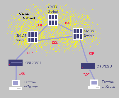
The first interface protocol is the
SMDS Interface Protocol, or SIP, which connects the CSU/DSU to the public network, thereby defining the subscriber network interface (SNI). This interface takes much of its design from the IEEE 802.6 Distributed Queue Dual Bus protocol, making SIP a very robust protocol. the SIP interface is fundamental to SMDS, since almost all of the other protocols are (at least partially) based on SIP.
The next interface is the
Data Exchange Interface (DXI), which connects the customer's equipmentto the CSU/DSU. This protocol is based upon the widely used HDLCv protocol. One motivation for the creation of the DXI interface is the complexity of SIP due to the IEEE 802.6 DQDB standard. The DQDB standard requires that many features that are of questionable value to SMDS be implemented, increasing the cost of implementing SMDS. Some SMDS providers now offer DXI as the primary interface between the customer's equipment and the public network, in order to reduce cost.
Another interface, not shown in the figure above, allows users of Frame Relay equipment to access SMDS networks. This interface, called
SIP Relay, encapsulates SIP frames within Frame Relay's LAPF protocol. These framed are delivered to a interface within the providers network where they are placed on the SMDS network.
An interface that is gaining in popularity is the
ATM interface. The ATM interface replace SIP as the subscriber network interface, allowing SMDS service to be provided over ATM networks. This is accomplished by replacing the lower layers of SIP with ATM layers.
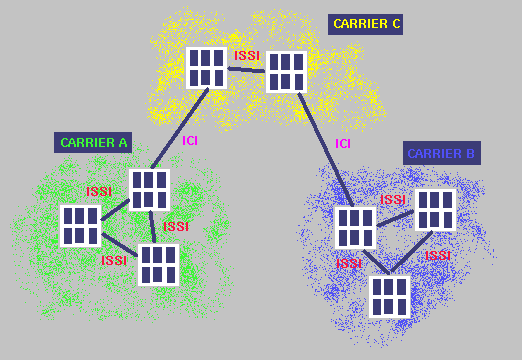
Within the public network, the
InterSwitching System Interface (ISSI) connects the individual SMDS switches. ISSI includes other functions relevant to the provider, including routing and maintenance functions. In addition to ISSI, there is another interface used within the public network, called the
InterCarrier Interface (ICI). ICI is used to make connections between different SMDS service providers, such as between a local SMDS provider and a long distance provider. A conceptual model of the ICI interface is illustrated in the figure below:
Each SMDS message contains a source address and a destination address. The addresses are constructed as shown below:
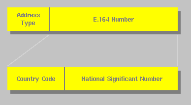
An SMDS address is constructed of two fields: a four bit address type and a variable length E.164 address. The address type field indicates one of two address types: individual or group. Individual addressing is implies a single source, single destination message. Group addressing allows a single source to send identical packets to a number of destinations. Group addressing is performed by allocating a dedicated address to represent a group of machines. These addresses are semi-permanent, since they must be allocated by the service provider. The E.164 address consists of two fields: a country code and a national significant number. These fields together create the address of the actual subscriber network interface (or group, in the case of a group address). Multiple addresses per SNI are allowed. For a high speed connection (DS1 or greater), up to 16 individual and 48 group addresses are allowed per SNI. For low speed connections, up to 2 individual and 3 group addresses per SNI are permitted.
Address Screening
Another feature of SMDS is the ability to screen the addresses of incoming and outgoing packets. An address screen can either limit packets to a set of allowed hosts, or list a series of forbidden hosts. Using this feature, subscribers can construct virtual private networks, preventing the loss of confidential data over the network.
Source Address Validation
Similar in operation to address screening, source address validation is a feature used by the service providers to ensure that frames injected into the network originate from valid address assigned to the appropriate SNI (subscriber network interface). This feature allows accurate billing information to be collected, as well as preventing "address spoofing", which would compromise the security provided by address screening.
A variety of different transmission technologies can be used with
SMDS, including DS1 (E1 in Europe), DS3 (E3 in Europe), DS3 based ATM, ISDN (Nx56kbps, Nx64kbps), and Frame Relay. Bandwidths range from 56kbps for ISDN access to 34Mbps for DS3 access. Higher bandwidth transmission technologies are expected in the future.
Since, in its initial offering, the physical medium used by SMDS was limited to either DS1 or DS3 (or E1 and E3, in Europe), a mechanism was required to provide users with intermediate data rates. This mechanism prevents users from having to pay for bandwidth that they cannot utilize, making SMDS more economical. These intermediate rates are called Access Classes.
Access Classes operate by limiting the the sustained information rate available to the user. This limit is only placed on traffic injected into the network, since limiting traffic leaving the network could lead to an excessive use of buffer space within the public network. The sustained information rate is limited using an algorithm called the credit manager algorithm. The algorithm works by requiring that outgoing packets have a certain amount of "credit" in order to be transmited. If a packet has sufficient credit, it is transmitted, and the required amount of credit is deducted from the total. If a packet does not have sufficient credit, it is discarded. Additional credit, up to a defined maximum, is allocated at the sustained information rate. The credit manager algorithm therefore allows short bursts to use the full bandwidth of the link, while limiting the sustained rate, based on the rate that credit is accrued.
There are five Access Classes defined for DS3, and four for E3. No Access Classes are defined for DS1 or E1, since smaller bandwidths were not deemed to be desirable (although slower connections to SMDS were later added. The access classes for DS3 are defined for sustained information rates of 4Mbps, 10Mbps, 16Mbps, 25 Mbps, and 34Mbps (full DS3). It is not accidental that some of these classes match the rates of existing LAN technologies. Similar access classes are defined for E3, and can be found in
[15].
SMDS is designed to be a reliable service. A set of steep quality of service objectives have been defined. However, the definitions in this section are just objectives, so real life use may not reach the stated goals. All of the objectives presented in this section are completely defined in
[15].
SMDS is designed to be operational 24 hours a day, 365 days a year, with no less that 3,500 hours between service outages. In the event of an outage, service should be restored within 3.5 hours. These goal imply that SMDS should be available 99.9% of the time. These goals should be better than leased line technologies, because SMDS packets can be routed around network failures. These objectives are defined for service through a single carrier, from one Subscriber Network Interface (SNI) to another.
Another set of objectives relate to the accuracy of the delivered information. These are expressed as probabilities of the defined event occuring. These objectives range from a probability of 1E-4 of a packet not being delivered to a probability of 5E-13 of a packet containing a bit error. Other objective include probabilities for misdelivered, duplicated, and missequenced packets.
The final set of performance objectives, and perhaps the most important, regard delays through the transmission network. The delays depend on a number of factors, including packet length and the type of SNI at the source and destination. For medium size packets (1600 bytes), delays range from 472ms for 56kbps to 56kbps transmissions, and 20ms for DS3 to DS3 transmissions. These times are expressed as 95th percentile delays (95% of packets will have a delay less than or equal to these figures). These delays are only defined for a local connection. If multiple carriers are used (i.e. long distance), the delays will be higher.
SMDS Specifications
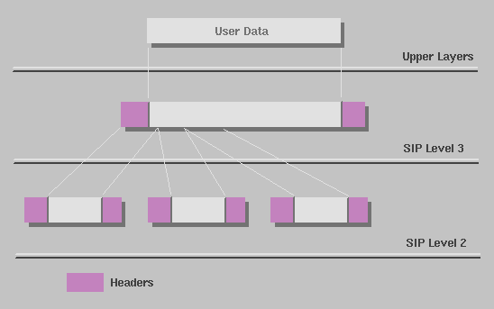
The SIP protocol is designed for the SNI (subscriber network interface). SIP is based upon the the IEEE 802.6 DQDB, and is defined in three layers.
SIP Level 3processes data frames from upper layers, which can be up to 9188 bytes in length.
SIP Level 2splits the Level 3 frames into a series of 53 byte packets.
SIP Level 1is composed of two sublayers, Physical Layer Convergence Protocol (PLCP) and the Physical Medium Dependent Protocol. The PLCP defines how cells are mapped onto the physical layer, while the PMDP defines the actual physical medium. The functions of the individual layer are shown in the figure below.
SIP Level 3 accepts variable length data from higher layers, adding the appropriate header, frame check sequence, and trailer fields. The data field can be up to 9188 bytes in length. A pad field is used to to ensure that the data field ends on a four byte (32 bit) boundary. An optional CRC-32 field can be included to provide error checking. The header field is 36 bytes long, and includes source and destination addressing, length, carrier selection, and higher layer protocol information. A more complete description of the header fields can be found in
[15]and
[16].
SIP Level 2 segments the Level 3 frame into a series of short, fixed length segments designed for transmission over the telephone network. SIP Level 2 conforms to IEEE 802.6 DQDB, so hardware designed for DQDB can be used with SMDS
[16].
Each of the small segment is 53 bytes in length, and contains 44 bytes of data. The 44 bytes of data is preceded by 7 byes of header, and followed by a two byte trailer. The header contains fields for access control, network control (unused in SMDS), segment type (beginning of message, continuation of message, end of message), a sequence number, and a message identifier. The trailer contains a payload length field, indicating how much of the data in the segment is meaningful. the remainder of the segment holds a 10 bit CRC protecting the last 47 bytes of the segment (the first five bytes contain another CRC). A more complete description of these fields can be found in
[15]and
[16].
SIP Level 1 is responsible for placing the 53 byte segments created by
SIP Level 2onto the physical medium. A variety of different physical media are supported. In North America, the most common physical layer would be either DS1 (1.544 Mbps) or DS3 (44.736 Mbps). It is planned that SIP will be extended to support faster links, like OC3
[15], and, using the
DXI Protocolinstead of SIP, SMDS has been extended to slower bit rates. SIP Level 1 is composed of two sublayers, Physical Layer Convergence Protocol (PLCP) and the Physical Medium Dependent Protocol. The PLCP defines how cells are mapped onto the physical layer, while the PMDP defines the actual physical medium.
To facilitate the use of carriers' and users' existing frame relay equipment with SMDS services, the SIP Relay interface was created. In essence, SIP relay allows users to access a carrier providing SMDS service even if it is not available from the user's local carrier. On the Frame relay side,
SIP Level 3Frames are encapsulated within Frame Relay's LAPF (Link Access Protocol for Frame relay) frames. Within the carrier network, an interworking device exists that converts packets back and forth between the LAPF protocol and the SMDS protocols. To access the SMDS network, a frame relay user needs a permanent virtual circuit (PVC) established to the interworking unit. Then the user can send SMDS frames through the PVC and interworking unit into the SMDS network. This process is illustrated in the figure below:
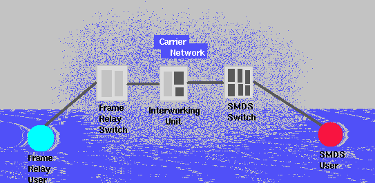
The SIP Relay protocol is composed of three layers, SRI Level 3, SRI Level 2, and SRI Level 1. SRI Level 3 is identical to SIP Level 3, while SRI Level 1 is any of the physical layers used by frame relay. SRI Level 2 is responsible for encapsulating the SIP Level 3 frames using LAPF. Further information on this interface can be found in
[15].
Since the
SIPprotocol is based on IEEE 802.6, it contains many infrequently used features, like the ability to have many hosts on a single link. These additional features have made the cost of implementing the SIP protocol quite high. These features predominate in
SIP level 2and
SIP level 1, where the DQDB protocols are used. To help control these costs, the data exchange interface (DXI) is a simple protocol developed to communicate between a customer's router and the CSU/DSU. Therefore, only the CSU/DSU is required to implement the full SIP protocol. Routers and terminals only require a small software upgrade to speak
SIP level 3. In a move to further reduce customer costs, MCI offers low speed (56/64kbps) SMDS service using DXI as the subscriber network interface, eliminating the need for the customer to purchase an expensive CSU/DSU altogether
[15].
The DXI protocol is designed to operate over a single link, and is based upon HDLC (High-level Data Link Control). HDLC frames are used to encapsulate
SIP level 3frames for transmission over the link. DXI is a two layer protocol, with a
DXI link layerand a
DXI physical interface.
As stated above, DXI uses traditional HDLC frames to transport SIP Level 3 information over the link. The figure below shows the HDLC frame structure used in the DXI protocol.
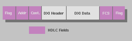
HDLC uses the binary flag "01111110" to delimit individual frames. Bit stuffing is used to prevent such a sequence from occurring within the data frame. In the DXI protocol, the address bits are used to divide the channel into a number of logical links, allowing individualized flow control for different messages. Other address bits are used to indicate the destination (either the router or the CSU/DSU) and to differentiate between command and date frames. A more complete description of DXI is given in
[15], and a thorough description of HDLC is given in
[17].
The DXI physical varies, depending upon the type of the subscriber's SMDS
Access Class. An interface commonly used for DS3 and E3 rates is the High Speed Serial Interface (HSSI), which can sustain DS3 data rates over a serial link.
SMDS service can be provded over ATM networks by using the ATM interface. This is accomplished by replacing the services defined in
SIPto ATM, using AAL (ATM Adaptation Layer) 3/4. This process is shown in the figure below
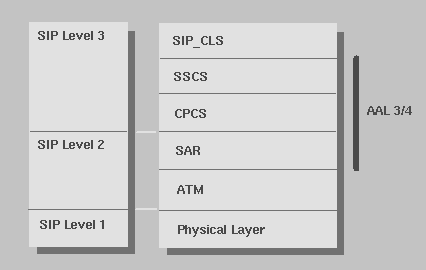
As shown above, SIP Level 1 is replaced by the ATM physical layer, SIP Level 2 by the ATM layer and the Segmentation and Reassembly (SAR) sublayer of AAL 3/4, and SIP Level 3 by the CPCS (Common Part Convergence Sublayer) and SSCS (Service Specific Convergence Sublayer) of AAL 3/4. Finally the SIP_CLS (SIP Connectionless Service Layer) provides the appropriate interface to the upper layers, hiding the ATM implementation from the user.
SMDS Specifications II
The ISSI protocol defines the interface between two SMDS switches. ISSI is a three level protocol, with the uppermost layer independent of the transmission technology and the lower two dependent upon the physical link. These three layers differ from the three layers defined in
SIP
[16].
ISSI Level 3 is defined as a resource capable of sending a variety of packets through the network
[15]. This layer provides services like packet forwarding, packet relaying, packet routing, congestion control, and route management. It also provides connectionless point to point and multicast services to higher layers, which use these services to manage the network.
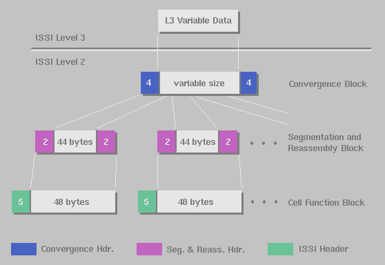
ISSI Level 2 is based upon IEEE 802.6, like most of the other protocols presented here. Its purpose is to transmit higher layer data between switches. ISSI Level 2 performs functions similar to those in both
SIP Level 3and
SIP Level 2, including bit error detection, framing, and segmentation and reassembly. These functions are split between three sublayers: Convergence Functions Block, Segmentation and Reassembly Block, and Cell Functions Block. The tasks performed by these sublayers are depicted in the figure below:
ISSI Level 1 provides ISSI Level 2 with an interface to the physical transmission medium. In North America, two types of ISSI Level 1 are currently defined for SMDS: one for DS3 links, and one for SONET STS-3c links. Like
SIP Level 1, ISSI Level 1 is divided into two sublayers, the Physical Layer Convergence Protocol (PLCP) and the Physical Medium Dependent Protocol (PMDP). The PLCP sublayer is concerned with mapping the PMDP services to a generic physical layer interface, while he PMDP layer manages the physical link. the PLCP sublayer for DS3 and STS-3c conforms to IEEE 802.6.
The ICI interface is used as an interface between two different SMDS service providers, either between two LATAs (Local Access Transport Area), a LATA and an IEC (Inter Exchange Carrier), or two IECs. The ICI protocol defines a number of services
[16], including:
- Establishing SMDS Service through the exchange.
- Terminating SMDS Service through the exchange.
- Transmission of service specific information (i.e. user data).
- System management.
The ICI protocol is a connectionless, point to point protocol for variable length data. It provides addressing, framing, and error detection. The ICI protocol is composed of three layers. the first layer, ICI Level 1, handles physical layer interfacing functions. The second layer, ICI Level 2, performs segmentation of outgoing frames and reassembly of incoming packets. The final layer, ICI Level 3, performs frame addressing functions and functions specific to higher level services.
Who Is Using SMDS?
SMDS, although gaining in popularity, suffers from a number of problems and misconceptions. Many users are reluctant to invest in SMDS, given the excitement surrounding ATM
[29]. In addition, many service providers do not place much marketing emphasis upon SMDS, and instead push Frame Relay technologies
[5]
[9]
[23]. Many users are also turned off by the cost of SMDS
[22]
[26], although the cost per unit of bandwidth is very economical compared to other technologies with equivalent bandwidths. Some descriptions of SMDS in the popular media are technically inaccurate, and make meaningless comparisons between services
[23].
Despite these problems, the organizations actually using SMDS give it excellent reviews
[2],
[4],
[11],
[12],
[14],
[21],
[27]. All of these case studies have a common theme: SMDS was used for LAN interconnection over long distances, providing flexible, high-bandwidth connections between multiple sites. Users were quite happy with the ease of configuration and network management. From these case studies, it can be seen that SMDS is most economical when many sites acre connected together. Using SMDS for a simple point to point connection does not justify the tariffs or the required investment in equipment.
SMDS Bibliography
- WilTel, MCI Propel SMDS Nationwide,InfoWorld,December 20, 1993.
Not Found
- Beth Davis, Printer Extends Its Use Of SMDS Net,Communications Week,December 12, 1994.
Case Study
- Downey Invests $1.5 M to Link 52 Branches,American Banker,November 23, 1994.
Not Found
- David Rohde, SMDS, Switched LANS Win Battle For SchoolNet,Network World,November 21, 1994.
Case Study
- Annie Lindstrom, Frame Relay and SMDS - Unlocking the Marketing Challenge,Telephony,November 21, 1994.
Good presentation of marketing problems of SMDS
- Kevin Tanzillo, Bank Enthused Over SMDS, Eyes ATM Arrival,Communications News,November 1994.
Not Found
- Fred Goldstein and Jim Metzler, Evaluating Network Services in the 1990s,Telecommunications,November 1994.
Not Found; probably good
- Annie Lindstrom, Delaware Does Data,Telephony,October 3, 1994.
Not Found
- Annie Lindstrom, An SMDS Status Report, Telephony,September 19, 1994.
News bite describing marketing woes of SMDS
- Eric Paulak, Why Use Private Lines When You've Got SMDS?,Network World,September 12, 1994.
News Bite
- SMDS: A Pleasant Surprise,Information Week,August 15, 1994.
Case Study
- Co-Net Expands SMDS Offerings, Communications Week,August 8, 1994.
Case Study
- Meridian Bancorp Invests in SMDS,Communications News,July 1994.
Not Found
- Annie Lindstrom, Prepress Graphics Company Adopts Low-Speed SMDS for Data Transfer,Communications Week,June 13, 1994.
Case Study
- Robert Klessig and Kaj Tesink,Wide-Area Data Networking with Switched Multi-megabit Data Service,Prentice Hall, 1995.
Excellent source; Covers every possible detail.
- Balaji Kumar,Broadband Communications,McGraw Hill, 1995.
Good treatment of broadband technology. 2 chapters on SMDS
- William Stallings,Data and Computer Communications,3rd Edition, Macmillan, 1991.
Good for genral networking concepts; no SMDS
- Jerry Cashin, Fleet networks prepare for takeoff in speedy-greedy shops,Software Magazine,April 1995.
Survey of high speed networking; technically inaccurate
- Sara Humphry, SMDS: Wide-area Data Networking with Switched Multi-Megabit Data Service,PC Week,Book reviewMarch 6, 1995.
- Mike Witt, Managing SMDS devices via in-band SNMP,Telecommunications,March 1995.
good overview of SMDS network management
- Russ Sharer, The data doctor is in,LAN Magazine,Feb 1995.
Case study (short)
- Mollenauer, James F., The zen of SMDS: what is the sound of one wing flapping?,Telecommunications,Feb 1995.
OK SMDS evaluation. includes price comparison
- Rowles, Richard, SMDS in '95: The year of the public packet-switched network,MacWEEK,Dec 12, 1994.
Good high level description, including marketing problems.
- Westmoreland, Nicole, Catalog printer finds less stress with SMDS,MacWEEK,Dec 12, 1994.
Case Study
- Davis, Beth, Nationwide SMDS still a ways away,Communications Week,Nov 21, 1994.
News bite on marketing woes.
- SMDS is here: Where are the customers?,Data Communications,Oct 1994.
News bite on european pricing
- Masud, Sam, NASA won't wait for ATM; Goddard Space Flight Center chooses connectionless SMDS for metro lines.,Government Computer News,August 8, 1994.
Case study
- Taylor, Steven, ATM, frame relay, SMDS .... Who cares?,Data Communications,August 1994.
Column; only got abstact; mostly opinions.
- "No respect at all: though widely implemented, SMDS is upstaged by Frame Relay and ATM,LAN Computing,August 1994.
Comparison to frame relay and ATM; marketing woes
- cell-relay-faq,
http://cell-relay.indiana.edu/cell-relay/FAQ/ATM-FAQ/FAQ.html :
FAQ on cell relay networks, inc. LANs & WANs; Mostly ATM
Michael Iverson, August 21, 1995
Other Reports on Recent Advances in Networking 1995
Back to Raj Jain's Home Page