Frame Relay Networks - a survey
Viswanath Subramanian
vsubrama@cse.wustl.edu
It is a broad survey of Frame Relay Networks - both from a designer's and user's perspective. It includes a bibliography and a set of WWW sites with information on Frame Relay Networks.
Last Modified Aug. 25, 1995
Table of Contents
- Introduction to Frame Relay Networks
- The Frame Relay Protocol
- LAN Interconnection with Frame Relay
- Frame relay and ATM
- The Future
- Bibliography
Today's communication networks are built using digital trunks that are inherently reliable, while providing a high throughput and minimal delay. The traditional approach to packet switching (X.25), used in-band signaling, and includes end-to-end and well as per-hop flow control and error control. This approach results in considerable overhead. Frame relay is a packet-mode transmission service that exploits characteristics of modern networks by minimizing the amount of error detection and recovery performed inside the network. Thus , by streamlining the communications process, lower delay and higher throughput is achieved.
Frame relay offers features that make it ideal to interconnect LANs using a Wide Area Network (WAN). Traditionally, this was done using private lines, or circuit switching over a leased line. However, this method has several drawbacks, mainly that it becomes prohibitively expensive as the size of the network increases - both in terms of miles and number of LANs. The reason for the high-cost is that high-speed circuits and ports must be setup on a point-to-point basis between an increasing number of bridges. Also, circuit-mode connectivity results in a lot of wasted bandwidth for the bursty traffic that is typical of LANs.
On the other hand, traditional X.25 oriented packet switching networks entailed significant protocol overheads and have historically been too slow - primarily supporting low-speed terminals at 19.2 kbs and lower. Frame relay provides the statistical multiplexing interface of X.25, without its overhead. Besides, it can handle multiple data sessions on a single access line, which means that hardware and circuit requirements are reduced. Frame relay is also scalable - implementations are available from low bandwidths (eg, 56 kbps), all the way up to T1 ( 1.544 Mbps ) or even T3 ( 45 Mbps ) speeds.
In this survey, we first describe the nature of frame relay in some detail, then a users' perspective of how to make frame relay work for them, and finally a look at how frame relay operates with ATM.
Table of Contents
2. The Frame Relay Protocol
In this section, we discuss the nature of the service that frame relay provides. Frame relay provides a
connection-orientedlink-layer service with the following properties:
- Preservation of the order of frame transfer from one edge of the network to the other
- Non-duplication of frames
- Small probability of frame loss
The fact that FRBS need not provide error detection/correction and flow control relies on the existence of intelligent end user devices, the use of controlling protocol layers, and high-speed and reliable communication systems. Access to the FRBS is via a frame relay interface defined between a date circuit-terminating equipment (DCE) on the network side and data terminal equipment (DTE) on the user side. While the Frame Relay standard specifies methods for setting up and maintaining both switched virtual circuits (SVCs) and permanent virtual circuits (PVCs), most implementations support only PVCs. In 1990, four vendors - StrataCom, Digital Equipment Corporation, Cisco Systems and Northern Telecom - collaborated on developing a specification called the Frame Relay Specification with Extensions[]. This document introduced a Local management Interface (LMI) to provide control procedures for permanent virtual circuits (PVCs). It is structured in to a basic mandatory part and a number of optional extensions. The control procedures form three main functions:
- Link integrity verification initiated by the user device and continuously maintained.
- When requested by the user, full status network report providing details of all PVCs.
- Notification by the network of changes in individual PVC status, including the addition of a PVC and a change in PVC state (active/inactive).
ANSI and ITU-T define frame relay on ISDN. The Frame Relay forum has implementation agreements on various physical layers, including V.35 leased lines (56 kbps), T1, and G.704 (2.048 Mbps) . Generally, public carriers offer frame relay services from speeds of 56 kbps to T1/E1 speeds. Private networks can be implemented at higher and lower speeds.
Table of Contents
Transmission
For transmission of data between end-users, the protocol used is Q.922, which is an enhanced version of LAPD. Only the core functions of Q.922 are used for frame relay:
- Frame delimiting, alignment and transparency (using HDLC flags)
- Frame multiplexing and demultiplexing using the address field.
- Aligning frame boundaries
- Inspecting the frame to ensure that it is not too long or too short
- Detection of transmission errors using a frame check sequence (FCS)
- Congestion Control functions
Signaling is done using reliable LAPD.
Frame Relay Frame Formats
Two Byte Format
8 7 6 5 4 3 2 1 ---------------------------------------------------------- | | | | | DLCI (high order) | C/R | EA | | | | | ---------------------------------------------------------- | | | | | | | DLCI (low order) | FECN | BECN | DE | EA | | | | | | | ----------------------------------------------------------
Three Byte Format
8 7 6 5 4 3 2 1 ---------------------------------------------------------- | | | | | DLCI (high order) | C/R | EA | | | | | ---------------------------------------------------------- | | | | | | | DLCI | FECN | BECN | DE | EA | | | | | | | ---------------------------------------------------------- | | | | | DLCI (low order) or DL-CORE Control | D/C | EA | | | | | ----------------------------------------------------------
Three Byte Format
8 7 6 5 4 3 2 1 ---------------------------------------------------------- | | | | | DLCI (high order) | C/R | EA | | | | | ---------------------------------------------------------- | | | | | | | DLCI (low order) | FECN | BECN | DE | EA | | | | | | | ---------------------------------------------------------- | | | | DLCI | EA | | | | ---------------------------------------------------------- | | | | | DLCI (low order) or DL-CORE Control | D/C | EA | | | | | ----------------------------------------------------------
Most of the header represents the data link control identifier (DLCI), which identifies the frame's virtual circuit. It might be 2, 3 or 4 octets in length. An extended address bit (E/A) is reserved in each octet to indicate whether or not the octet is the last one in the header. The DLCI influences the routing of the frame , and is also used to multiplex PVCs onto the physical link and enables each endpoint to communicate with multiple destinations by means of a single network access. DLCIs may have either local or global significance in the network. The main difference between the frame format used and lAPD is the absence of a control field. This has the following implications:
- There is only 1 user type, used for carrying data.
- In-band signaling cannot be used.
- There are no sequence numbers, so no error control or flow control can be done.
The forward explicit congestion notification (FECN) and the backward explicit congestion notification (BECN), as well as the Discard eligibility (DE) bit are explained in the next section.
Each frame has a 16 bit Frame Check Sequence (FCS). Error frames are to be discarded. The length of the FCS generally limits the frame size to 4096 bytes.
For interface management purposes, the frame relay interface includes control procedures based on the LMI definition contained in the original multivendor specification. The procedures use messages carried over a separate PVC identified by an in-channel signaling DLCI. The management frames are transferred using data link unnumbered information frames, similar to the Q.931 format.
Table of Contents
Congestion Control
Objectives
The objectives for frame relay congestion control are specified as follows:
- Minimize frame discard.
- Maintain, with high probability and minimum variance, the agreed upon quality of service.
- Minimize the possibility of one end user's monopolizing network resources at the expense of other end-users. (Fairness)
- Overhead on end-users should be limited.
- Limit the spread of congestion to other networks and other elements in the network
- Operate effectively regardless of traffic flow in either direction between end-users.
Congestion-avoidanceprocedures are used at the onset of congestion to minimize the effect on the network. This requires explicitsignaling by the network.
Congestion-recoveryprocedures are used to prevent network-collapse in the face of severe network congestion. These procedures are typically initiated when the network has begun to drop frames, which must be reported by some higher level of software and serve as an implicit signalingmechanism.
Congestion Avoidance with explicit signaling
For explicit signaling 2 bits in the address field of each frame are provided. They are set by any frame handler that detects congestion. They constitute signals from the network to the end-user. They are:
- Backward explicit congestion notification (BECN):This is set by the network when a frame traverses a congested virtual circuit in the opposite direction. A source that detects it is transmitting on a congested path and is expected to reduce load.
- Forward explicit congestion notification (FECN):This allows the destination to discover that the path is congested and to notify the source transport to decrease its window and thus place less demand on the network. In OSI and DECnet Phase V environments, this bit can be mapped onto the congestion experienced bit in the header of the network layer PDU.
Congestion Recovery with implicit signaling
Implicit signaling occurs when the network discards a frame and this fact is detected by the end-user at a higher layer. The ANSI standard suggests that a user that is capable of varying the flow control window size use this mechanism in response to implicit signaling.
The user can also provide the network with some guidance about which frames to drop. The
discard eligibilitybit is used for this purpose. The DE capability makes it possible for the user to temporarily send more frames than it is allowed to on the average. In this case the user sets the DE bit on excess frames. The network will forward these frames if it has the capacity to do so.
The DE bit can be used also to serve as a tool for providing a guaranteed level of service. This tool can be used on a per-logical connection basis to ensure that heavy users can get the throughput they need without penalizing lighter users. The mechanism works as follows: each user negotiates a
committed information rate (CIR)(in bits per second) at connection-setup time. This is an estimate of the normal traffic during a busy period. The frame handler to which the user station attaches then meters the user's rate, and sets the DE bit if the user is sending data at a rate exceeding CIR A maximum rate is defined, such that any frames above the maximum are discarded by the frame handler.
The way this is implemented is that the frame handler measures traffic over each logical connection for a time interval Tc, which is set by the network. Accordingly, 2 parameters are negotiated. The
committed burst size (Bc)is the maximum amount of data that the network commits to deliver over a logical connection during an interval Tc. The
excess burst size (Be)is the maximum amount of data by which a user can exceed Bc during an interval Tc - these data are delivered at a lower probability than the data within Bc.
The ANSI specification suggests the use of a leaky bucket algorithm for monitoring flow. The frame handler records the cumulative amount of data sent by each user in a counter, C. The counter is decremented at a rate of Bc every Tc time units. Whenever the counter value exceeds Bc but is less than Bc + Be, incoming data are in excess of the committed burst size and are forwarded with the DE bit set. If the counter reaches Bc + Be, the frame is discarded.
Table of Contents
Multiprotocol Encapsulation over Frame Relay
When different protocols are run over frame relay, we must specify how to encapsulate them so that the protocol being used can be identified. The Frame Relay Forum reached an agreement on the possible encapsulation methods used. The actual method used on a given PVC must be configured when it is set up. For SVCs this is established during call setup.
This is don by adding a header to the frame relay payload. Three header formats are recognized:
- Direct Network Layer Protocol Identifiers (NLPID) - protocols for which an NLPID value is defined in ISO TR 9577: e.g., IP, CLNP (ISO 8473),
- SNAP encapsulation - using SNAP NLPID followed by SNAP: LAN bridging, Connectionless protocols which have a SNAP value (e.g., DECNET, IPX, AppleTalk etc.).
- NLPID followed by four octets indicating layer 2 and layer 3 identifications: connection oriented protocols (e.g., ISO 8208, SNA, etc.) and other protocols which can't be supported by the other methods.
Table of Contents
Multicasting
The Frame Relay Forum has specified a standard way of implementing multicast services over a PVC. These services must be pre-configured by a network administrator. The model used is based on the X.6 Multicast Service Definition.
The multicast service model shows a
multicast groupconsisting of
membersthat participate in a multicast communication using an intermediate entity called the
multicast server. The multicast server is a logical entity which provides the multicast service to all members. Figure 1 illustrates the multicast service model.
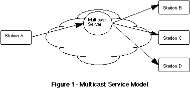
Figure 1
- Multicast Service Model
The multicast server may be a centralized server as shown in figure 1 or it may be a distributed service with several units providing the multicasting function. There is no limit to where the multicast servers reside (either internal to, or outside of the network) but for the purposes of discussion, the multicast servers will be viewed as a single logical unit internal to the frame relay network.
There are three types of multicast service.
One-way Multicasting
In this configuration, one node acts as a root and the rest as leaves of a tree. This multicast service requires that the root have point-to-point frame relay connections established to all leaves in the multicast group. The root will also maintain a separate one-way multicast connection to the multicast server.
With this configuration, the root sends multicast frames via the one-way multicast connection identified by a one-way multicast DLCI (Mdlci). The multicast server will accept frames from the Mdlci and
will send the frame to each leaf member of the active multicast group.
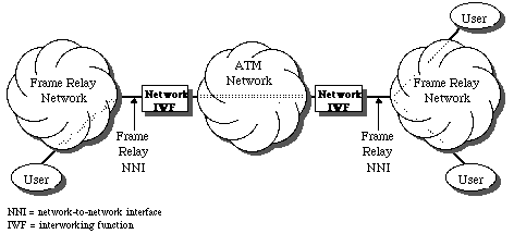
Figure 2
- One-Way Multicast
If the multicast group is spread over different networks, a slightly different model is used. The NNI acts as a root in the leaf networks.
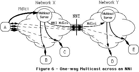
Figure 3
- One-way Multicast across an NNI
This service is useful in applications where the stations are routers or bridges. The multicast frame will typically be used for obtaining or verifying the presence or identification of the multicast group members.
Two-way Multicasting
The two-way multicast service provides for duplex transmissions. In one direction the data units are multicast, while in the other, they are concentrated. One participant in a two-way multicast connection is defined as the root; it functions to send the data units into the multicast server for multicasting. The rest of the participants are defined as the leaves. The following rules apply to the two-way multicast service.
- Any data units sent by the root are transmitted to all leaves in the active multicast group.
- Any data units sent by a leaf are transmitted to the root of the active multicast group, but not to the other leaves.
Figure 4 depicts the two-way multicast service.
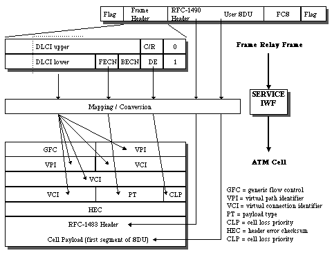
Figure 4
- Two-Way Multicast
This service is useful in an environment, where, the root does not need to communicate individually with the leaves and where the number of leaf stations prohibits the establishment of individual PVCs between the root and each of the leaves. For example, when using SDLC or similar polled protocols, there may be many terminals connected to a limited number of host ports. The host broadcasts to a group of terminals over a multi-drop line; only one terminal has permission to respond at a time. The two-way multicast service could be used to transparently replace multi-drop lines, between the host and terminals.
N-way Multicasting
The third multicast service is n-way multicasting. All transmissions in this scheme are duplex and all are multicast. All members of the multicast group are transmission peers. Any data sent on a n-way multicast connection is sent to every other member of the active multicast group.
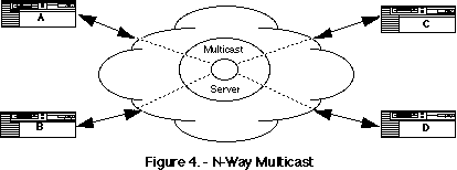
Figure 5
- N-Way Multicast
This type of multicast service is convenient for applications that require all participants to acquire the same data. One might envision this type of multicast for use with teleconferencing or routing update protocols.
Table of Contents
Customer Network Management (CNM)
The Frame Relay Forum and the Internet Engineering Task Force have jointly developed a standard SNMP Management Information Base (MIB) for Frame Relay CNM,
RFC 1604, "Definitions of Managed Objects for Frame Relay Service". By using this MIB, a customer's network management system (NMS) can monitor its PVCs, UNI ports, and NNI ports. This MIB is restricted to the customer's view of the network - management of lines, switches, etc. is not possible.
Since the provider Frame Relay network is a shared network amongst many Frame Relay customers, each customer will only be provided with access to their relevant information (e.g., information with respect to their interfaces and PVCs).
Typically, the customer's NMS will access the SNMP agent using SNMP over UDP over IP over Frame Relay. If a PVC spans multiple networks, the NMS must poll multiple proxy agents to retrieve an end-to-end-view of their PVC.
Table of Contents
3. LAN Interconnection with Frame Relay
Introduction to LAN Interconnection
In the past few years there have been important advancements in computer and communications technology that have reshaped the business environment. The decreasing cost of processing power has brought PCs and high powered work stations to the end user, resulting in a boom in the use of personal computers, workstations, and LANs that has altered the corporate information system. The major changes include the following:
- Corporate Structure:
Previously, information systems were constructed in a hierarchical structure with a centralized mainframe supporting a large number of users. With the advent of today's technology, distributed computing environments based on Local Area Networks are augmenting traditional hierarchical mainframe architectures. Now information flows on a lateral level (peer-to-peer) both within organizations and to outside groups.
- Bandwidth Requirements:
LANs have grown up from a conglomeration of PCs and intelligent workstations, thus pulling along with them the workstation applications with their expectations of quick response time and the ability to handle large quantities of data. The LAN pipeline, typically running at 4, 10 or 16 Mbps, is assumed to be available for these applications, so the applications typically transfer orders of magnitude more data per transaction than a typical terminal-to-mainframe transaction. Nevertheless, like their terminal-to-mainframe counterparts, the LAN applications are bursty applications, with long idle periods.
- Management Requirements:
The management requirements of today's networks are more complex than ever before. Each environment is a unique combination of multi-vendor equipment. Growth and change within a company can result in constant network modifications. The network manager is pressured to find a cost effective way to manage this complexity.
Table of Contents
Benefits of Frame Relay
Frame relay makes better use of bandwidth because of its statistical multiplexing and low-protocol overhead. As a result of this, the user sees the following benefits of frame relay:
- Reduced Internetworking costs.
When using a private frame relay network, multiplexing traffic from many sources over private backbone networks can reduce the number of circuits and corresponding cost of bandwidth in the wide area. Since multiple logical connections can be multiplexed onto single physical connection, access costs are also reduced. Equipment costs may be lowered by reducing the number of port connections required to access the network. For remote access devices, access line charges can be lowered by reducing the number of physical circuits needed to reach the networks.
- Increased Performance with Reduced Network Complexity.
Both by reducing the amount of processing (as compared to X.25) and by efficiently utilizing high speed digital transmission lines, frame relay can improve performance and response times of applications.
- Increased Interoperability via International Standards.
Frame relay's simplified link layer protocol can be implemented over existing technology. Access devices often require only software changes or simple hardware modifications to support the interface standard. Existing packet switching equipment and T1/E1 multiplexers often can be upgraded to support frame relay over existing backbone networks.
- Protocol Independence.
Frame relay can easily be configured to combine traffic from different networking protocols like IP, IPX and SNA. This is especially useful for companies which use SNA to communicate with a centralized mainframe, and have started using other protocols for client-server applications. Cost savings can be achieved by using frame relay as a common backbone for the different kinds of traffic, thus unifying the hardware used and reducing network management.
Frame relay is a good choice for a business if the traffic is unpredictable, high-volume, and bursty typically for applications like electronic mail, CAD/CAM ( Computer Aided Design, Computer Aided Manufacturing) applications, and client-server applications. It is excellent for medium-to-large sized networks with high mesh or star connectivity.
Frame relay may not be the best choice for continuous traffic applications like software co-development, multimedia, for transferring huge 100 Mb files, or for connecting slow, dumb terminals to a mainframe.
Table of Contents
Setting up Frame Relay
The Elements of Frame Relay
Frame relay networks are made up of frame relay access equipment, frame relay switching equipment and public frame relay services.
Frame relay access equipment is the customer premises equipment (CPE) that uses frame relay to send information across the wide area. Access equipment may be bridges, routers, hosts, packet switches, specialized frame relay "PADs" or any other similar devices. In general, the same frame relay access equipment may be used either with private network frame relay switching equipment or with frame relay services. Frame relay switching equipment is devices that are responsible for transporting the frame relay compliant information offered by the access equipment. Switching equipment may be T1/E1 multiplexers, packet switches, or any specialized frame relay switching equipment that implements the standard interface and is capable of switching and routing information received in frame-relay format. As mentioned earlier, the actual transmission of the frames may be accomplished in either variable-length information units (frames) or fixed-length information units (cells). This equipment is used in the creation of private or public frame relay networks, as the underlying technology is identical. Public service providers (carriers) offer frame relay services by deploying frame relay switching equipment. Both frame relay access equipment and private frame relay switching equipment may be connected to services provided by a carrier. The service provider maintains access to the network via the standard frame relay interface and charges for the use of the service.
Access Devices
Access to the frame relay service involves three elements: customer premises equipment (CPE), a transmission facility, and the network itself. The CPE may be any of the types of access equipment, such as a frame relay router, or even a private network switch with a frame relay interface. This equipment basically aggregates and converts data into frame relay packets. Typically, there are three kinds used - routers, bridges, and frame-relay access devices (FRADs).
Routers are generally versatile. They usually can handle traffic from other WAN protocols as well. They can usually re-route connections if a line goes down, and some also provide support for flow control and congestion control. They typically range in price from $2000 to $50,000.
Bridges are basically low-cost, unintelligent routers. They are easier to configure and maintain, and are typically used to tie a branch office to a hub location. They are generally not used in frame relay networks as often as routers. They range in price from $1000 to $15000.
FRADs are designed to aggregate and convert data into frame relay packets; they dont route traffic. They work well if a site already has bridges and routers, or for sending mainframe traffic over a frame relay network. They range in price from $5000 to $20,000.
The distinction between these devices are blurring as vendors combine their functions into a single device.
Along with an access device, one also needs a DSU/CSU, which codes and formats data for transmission over the WAN, maintains clock synchronization with the transmission line, etc. These are commonly available, especially for 56kbps or T1/E1 lines, with prices ranging from $500 to $1,500.
The Network
One needs to choose between a public frame relay service or a private network. Public carriers are usually more cost-efficient, but large corporations which need complete control over the network opt for a private network.
To set up a public-frame relay service, one must specify the PVCs, and the port speeds and CIR rates required.
Many vendors offer public frame-relay service. There are three kinds:
- The big long distance companies like AT&T, SPrint, MCI and WilTel.
- The regional Bells.
- Independent regional and alternative providers and value-added networks (VANs).
The choice between them is guided by the location of the office you want to interconnect. If they are spread widely across the country, a national provider is ideal; if they are located within a local area, choose a regional Bell; for extra services including configuration, maintenance and management, choose a VAN.
To build a private network, you needs to buy frame relay backbone switches or you can add a frame-relay card to a multiplexor, especially if you already use multiplexors to segment traffic onto your leased lines.
Table of Contents
4. Frame Relay and ATM
Overview
There is a general consensus that Asynchronous Transfer Mode (ATM) will be the dominant WAN technology of the future. Today, frame relay has a widely established base, while ATM has virtually none, but this will not be the case 5 years from now. Many consider frame relay to be an interim technology, however, it is clear that frame relay will be around for a while, so ATM and frame relay must coexist.
The important point to remember is that frame relay and ATM offer different services and are geared towards different applications. ATM is being touted for applications like imaging, real-time video, collaborative CAD which are too bandwidth intensive for frame relay. On the other hand, at T1 speeds and lower, frame relay uses bandwidth much more efficiently than ATM.
The Frame Relay Forum and the ATM Forum have been working to implement an industry-wide agreement that specifies interoperability between ATM and frame relay. The agreement envisages two models of interoperation. In,
Network Internetworking , ATM acts as a backbone to transparently transport frame relay traffic between frame relay entities..
Service Internetworkingdoes actual protocol conversion, so that frame relay and ATM switches can be "mixed and matched". Frame relay would be used for speeds up to T1, and ATM for anything higher. Thus, with service internetworking, frame relay and ATM entities can communicate transparently.
Table of Contents
Network Internetworking
Network Interworking facilitates the transparent transport of frame relay user traffic and frame relay PVC signaling (LMI) traffic over ATM. This is sometimes referred to as tunneling. This means that multiprotocol encapsulation (and other higher layer procedures) are transported transparently as they would over leased lines. An important application for this is connecting two frame relay networks over an ATM backbone network.

Figure 7
Example of Frame Relay/ATM Network Interworking
(Frame Relay Forum)
The ATM network is used in place of a transmission facility (leased line) to connect the two frame relay networks. Each frame relay PVC can be carried over an ATM PVC, or all of the frame relay PVCs can be multiplexed onto a single ATM PVC. This method of connecting frame relay networks may provide economic savings when compared to leased lines. This is especially true when the frame relay network-network interface(NNI) is operating at a low percentage utilization.
The following services of frame relay are supported:
- Variable length PDU formatting and delimiting
- Error detection
- Connection multiplexing
- Loss Priority Indication
- Congestion Indication (Forward and Backward)
- PVC Status Management
Table of Contents
Service Internetworking
Service networking applies to communication between a frame relay user and an ATM user. The communication is transparent, so one side does not know that the other is on a different network. This means that the ATM user does not use any frame relay specific services and vice-versa. The ATM user must use the AAL-5 based message mode, which is similar to the core frame relay service.
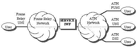
Figure 8
Example of Frame Relay/ATM Service Interworking
(Frame Relay Forum)
The main issue is conversion between the two formats. The frame relay (FR) packet is converted to an AAL5 data unit. The flags and insertion bits are deleted, the header is removed and some of the fields are mapped to ATM cell header fields. The frame delineation and 32-bit CRC of AAL-5 are added. In the ATM to FR direction, the message delineation of AAL-5 is used to detect frame boundaries, and the flags and CRC-16 are inserted. The congestion indication and discard eligibility bits of FR can be mapped to ATM cell header fields.

Figure 9
Service Internetworking Header Function Mapping
(Frame Relay Forum)
There is also a specification for a mapping the PVS management functions (LMI) of frame relay to those used in ATM. These include procedures for verifying link integrity, new/deleted PVCs and active/inactive PVCs.
Higher level protocol encapsulation is handled in two ways.
- Transparent Mode:
When the encapsulated protocol does not conform to the standards (eg. packetized voice), the encapsulations are forwarded without alteration
- Translation Mode:
If the encapsulated method corresponds to a standard specified in RFC 1493 (for ATM) and the Frame Relay Forum (eg. LAN to LAN traffic), then a mapping must be done between the two methods. The packets are encapsulated using NLPID for frame relay, and they use an LLC method for AAL-5.
Address resolution is done using the Address resolution Protocol (ARP)[RFC 826] and the Inverse ARP (InARP)[RFC 1293] protocol. These are done only for PVCs that are configured to be in the translation mode.
Table of Contents
5. The Future
The market for frame relay products and services is today estimated at $1.7 billion (by the end of 1995) and is expected to grow to $5 billion within the next 3 years. Carriers are rushing to add services, vendors are coming up with applications like voice over frame relay. The Frame Relay Forum is working hard at some features of frame relay to ensure its survival:
- Increased interoperability with ATM and other protocols.
- Defining specifications for frame relay at fractional T1 speeds.
- Working to anticipate a growth in demand as asynchronous analog lines are replaced by ISDN.
- Implementing dial-up SVC access to frame relay networks.
Table of Contents
6. Bibliography
Books
- Frame relay networks : specifications and implementations, by Uyless Black.
(McGraw-Hill, 1994, ISBN 0-07-005558-0).
A comprehensive and up-to-date treatment of everything you wanted to know about frame relay networks.
- ISDN and Broadband ISDN with Frame Relay and ATM, Third Edition, by William Stallings
(Prentice-Hall, 1995, ISBN 0-02-415513-6).
Another excellent book from Mr. Stallings. Comprehensive treatment of ANSI/CCITT standards for ISDN, SONET, Frame Relay and ATM. However, it does not cover Frame Relay Forum and ATM Forum agreements.
- Emerging Communications Technologies, by Uyless Black
(Prentice-Hall, ISBN 0-13-051500-0), c1994.
An excellent overview of new LAN and WAN communication technologies and standards.
- SNMP, A Guide To Network Management, by Dr. Sidnie Feit, 674 pages
(McGraw-Hill, c1995. ISBN 0-07-020359-8).
The bible of network management.
- The Basics Book of Frame Relay
(Motorola University Press, 1993, ISBN 0-201-56377-0, MUP-56-377)
In the tradition of Motorola's basic book series - a quick and easy to read introduction to the concepts of frame relay networks.
- The Guide to Frame Relay and Packet Networking
by Nathan J. Muller and Robert Davidson, 232 pages
Table of Contents
Articles
- "Special Report, Frame Relay"
, Communications Week, July 24th, 1995 .
The very latest industry perspective of frame relay.
- McParland, Micheal and Wilansky, Ethan,
"Running the Frame Relay Race"
, Byte, Nov. 1994.
Find out the ups and downs awaiting you when you use frame relay for LAN-WAN connection.
- Bharat T. Doshi and Pravin K. Johri,
"Communication protocols for high speed packet networks,"
,Computer Networks and ISDN Systems , vol. 24, pp. 243--273, May 1992.
A comprehensive treatment of the new approach to network protocols for new communication technologies. Particular attention is given to switching, error recovery, flow control and congestion control.
- Ben. Lisowski and Louise. Reingold,
"Sprint's evolution to broadband ISDN," IEEE Communications Magazine"
, IEEE Communications Magazine, vol. 30, pp. 28--30, Aug. 1992.
A good description of how carriers are reacting to broadband technology.
- Moe Rahnema,
"Frame relaying and the fast packet switching concepts and issues"
, IEEE Network, vol. 5, pp. 18--23, July 1991 .
Good overview of the concepts behind fast packet switching and frame relay.
- Harry Santoso and Serge Fdida,
"Frame relay: a solution for high bandwidth networking"
, Computer Communications, vol. 17, July 1993.
- Robert J. Roden and Deborah Taylor,
"Frame Relay Networks"
, Digital Technical Journal, vol. 5 No 1, Winter 1993.
Description includes DEC's frame relay products and services.
Table of Contents
ANSI and ITU-T standards
- International Telegraph and Telephone Consultative Committee,
"ISDN Data Link Layer Specification for Frame Mode Bearer Services",
CCITT Recommendation Q.922, 19 April 1991.
- American National Standard For Telecommunications - Integrated Services Digital Network - Core Aspects of Frame Protocol for Use with Frame Relay Bearer Service, ANSI T1.618-1991, 18 June 1991.
Table of Contents
- 1604PS T. Brown, "Definitions of Managed Objects for Frame Relay Service",03/25/1994. 46 Pages
(Obsoletes RFC1596)
- 1596PS T. Brown, "Definitions of Managed Objects for Frame Relay Service",03/17/1994. 46 Pages
(Obsoleted by RFC1604)
- 1586I O. deSouza, M. Rodrigues, "Guidelines for Running OSPF Over Frame Relay Networks",03/24/1994. 6 Pages.
- 1490DS T. Bradley, C. Brown, A. Malis, "Multiprotocol Interconnect over Frame Relay",07/26/1993. 5 Pages
(Obsoletes RFC1294)
- 1483PS J. Heinanen, "Multiprotocol Encapsulation over ATM Adaptation Layer 5",07/20/1993. 16 Pages
- 1315PS C. Brown, F. Baker, C. Carvalho, "Management Information Base for Frame Relay DTEs",04/09/1992. 19 Pages
- 1294PS T. Bradley, C. Brown, A. Malis, "Multiprotocol Interconnect over Frame Relay",01/17/1992. 28 Pages
(Obsoleted by RFC1490)
Table of Contents
Web Resources
Table of Contents
Viswanath Subramanian
vsubrama@cse.wustl.edu
Back to CIS 788 papers
Last Modified Aug. 25, 1995


