Difference between revisions of "Matlab Fanuc Robot Control"
From ESE497 Wiki
Jump to navigationJump to search| Line 1: | Line 1: | ||
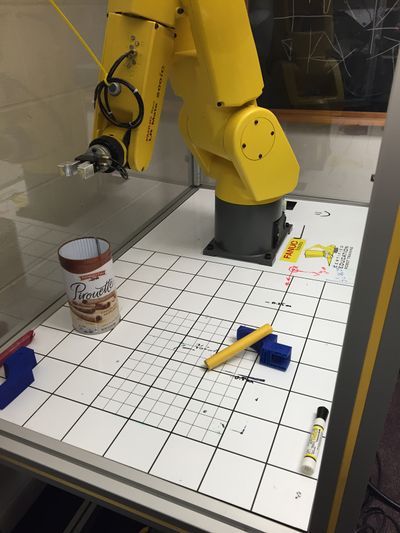
[[File:IMG_1188.JPG|400px]] | [[File:IMG_1188.JPG|400px]] | ||
| − | * Place marker | + | * Place marker and metal can exactly as shown above |
* Turn on Robot | * Turn on Robot | ||
** Menu -> Setup -> Frames | ** Menu -> Setup -> Frames | ||
| Line 7: | Line 7: | ||
** Select -> LV_COM_FRM to select the Teaching Pendant Program to run the robot to PC communication program | ** Select -> LV_COM_FRM to select the Teaching Pendant Program to run the robot to PC communication program | ||
** Turn Teaching Pendant to OFF | ** Turn Teaching Pendant to OFF | ||
| − | ** Insert key into Controller and turn to T1 position | + | ** Insert key into Controller and turn to T1 position |
** Press Shift -> Reset on Teaching Pendant to clear any errors | ** Press Shift -> Reset on Teaching Pendant to clear any errors | ||
** Press Green Start button on Controller | ** Press Green Start button on Controller | ||
Revision as of 21:31, 2 October 2015
- Place marker and metal can exactly as shown above
- Turn on Robot
- Menu -> Setup -> Frames
- Verify Tool Frame 1 is set to [0,0,0]
- Verify Tool Frame 2 is set to [0,0,95.3] so that the TCP is at the end of the gripper
- Select -> LV_COM_FRM to select the Teaching Pendant Program to run the robot to PC communication program
- Turn Teaching Pendant to OFF
- Insert key into Controller and turn to T1 position
- Press Shift -> Reset on Teaching Pendant to clear any errors
- Press Green Start button on Controller
- Menu -> Setup -> Frames
- Download and extract MatlabLabVIEWFanuc.zip
- Open and run LabVIEW\MatlabLabVIEWFanuc.vi
- Open and run matlab\MatlabLabVIEWFanuc.m
