Duckling
Link to Log
Project Proposal
Overview
There once was a time when children's toy cars would be bland and boring. A child might push the car and chase it, or use her own remote controller to move the car around, but no real fun was to had when the car couldn't move freely! We wish to fix this lack of fun by designing an entirely new kind of car-the kind of car that chases you! By integrating remote-controlled car, raspberry pi, and arduino, we plan to design a pi car so that its sensors (through the Pi camera) may evaluate a person's movement and follow them. The arduino will direct the car by communicating with the motor, servo and ESC . All components will be mounted on top of the car to create one autonomous system that needs no outside influence, besides a person's movements, to direct its path.
Team Members
Tushar Menon
Matheus Camacho
Tony Sancho (TA)
Objectives
The duckling project will be deemed a success if
1. The duckling's pi car is constructed successfully according to the reference guide
2. The pi car is able to sense a red dot (or other comparable reference point) and move towards it
3. The raspberry pi successfully connects to a pi camera
4. The sensors can differentiate between the movements of a target person or object and other movements.
5. The duckling pi car will move according to information from the camera
6. The duckling pi car will use the camera to follow a person
Presentation
Challenges
We expect our challenges to include:
1. Completing our project under budget
2. Learning how to use the raspberry pi and arduino
3. Interfacing the pi and arduino with one another
4. 3-D printing. No members have experience.
5. Getting the camera to communicate with the raspberry pi
6. Working with the PI camera image processing to sense a person
7. Difficulties with hardware assembly
We also expect that we may have difficulty working on the project independently if we do not all have access to the pi car with the arduino and raspberry pi mounted on top. We plan to leave it in the lab in order to protect our project and promote inclusivity in access. We have no concerns regarding privacy, user safety, or security from malicious attacks.
Gantt Chart
References
Budget
Dromida 1/18 Buggy($99)
ISC25 Rotary Encoder($40)
32GB MicroSD Card($13)
IMU 9DoF Sensor Stick($15)
Raspberry Pi Camera Module V2($30)
Brushed ESC Motor Speed Controller($6)
TowerPro SG90 Micro Servo($4)
TFMini - Micro LiDAR Module($40)
Arduino (free from lab)
Raspberry Pi (free)
Total: $247
Supplies purchased according to source: https://picar.readthedocs.io/en/latest/chapters/usage/mechanical.html#design
Design and Solutions
Building the car
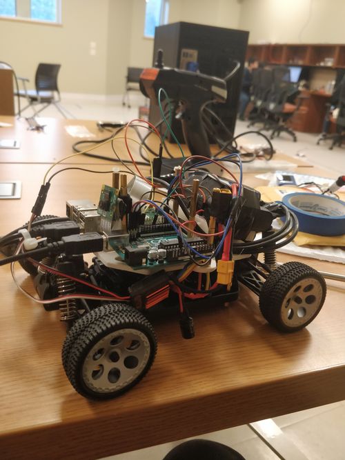
We bought a Dromida buggy and dismantled it to create our chassis for the car. We took out its batteries and motor, and replaced them with our own battery and motor. We connected the motor to an electronic speed controller, and also mounted a rotary encoder onto the chassis by drilling and dremeling through it. This forms Layer 0 of the car. We created a GND and 5V channel using breadboard and used spacers to mount the raspberry Pi and Arduino onto the first printed layer and then mounted that layer onto the car. We would have mounted the Lidar module onto the second layer, but we decided against its functionality to meet our objectives. A more detailed overview of the mechanical assembly can be found at the Pi car documentation
ESC, motor, encoder and servo connection
This is how the components were connected. (Credit to Zimon from the other Pi car group for the picture)
Pi and Arduino connection
We initially planned to implement a serial port between the Pi and Arduino, but decided to use I2C communication instead, using the code on this website, wiring them as follows
Code
https://github.com/Matheus-camacho/ese205
3D printed parts:
Encoder Mount: https://a360.co/2DUNNK6
First Layer: https://a360.co/2RquoDs
Second Layer: https://a360.co/2OBMGmP
Results
Final build
Here is what our final build of the car looks like
Demonstration
A demonstration of the car following a red object
Discussion
Our car had a successful demo, as outlined by our initial objectives. It moves smoothly and follows objects as intended. The only difference is that we chose not to use the kinect but that didn't change the functionality of the car. The reason for that is that a kinect is expensive and its hard to obtain a second hand one. Furthermore it's hard to interface the kinect with the Raspberry Pi, so we chose to use to use a Pi camera instead. We also could not add depth mapping functionality (we intended to use a lidar module in place of the kinect) because the getting the motor and encoder to work was a lot harder than we foresaw.


