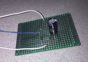
Full Bridge Rectifier Assembly
Revision as of 15:42, 4 May 2018 by Krwilliamson (talk | contribs)
Materials Needed
- Diode x4
- Breadboard
- Soldering Equipment
- Insulated wire (at least 3 distinct colors recommended)
Purpose and use
A full bridge rectifier converts alternating current to direct current. This is useful and necessary if you are trying to utilize power generated by an alternator or even from the power-grid.
Assembly
- You will be soldering the diodes to the breadboard according the the following circuit diagram.
- As you already know, diodes only allow current to flow in one direction. The diagram represents the directional current by the direction the arrows point. In person, the diodes will have a black stripe closer to one of the ends, this is the direction which current will flow.
- Solder the diodes into the breadboard as shown in the diagram.
- Solder a white wire into the D4-D1 junction and the D3-D2 junction. This will be where the alternating current is put into the rectifier.
- Solder a red wire into the D1-D3 junction, this will be the output of positive direct current.
- solder a black wire into the D4-D2 junction. this will be the negative end of the direct current output.

