Library Chair
Contents
Overview
The Library Chair is designed to make every library function more efficiently. The library chair design is based on a pressure sensor, which tells whether or not the particular chair is occupied, and then relays the information to a computer, which then compiles information from all of the library chairs. The computer then produces a map of the library and its chairs, and shows which chairs are currently unavailable. This way, each library attendee will know whether or not they will be able to find a seat in the library.
Team Members
Josh Zucker
Nick Blenko
Tom Howe
Our wonderful TA, Mo!
And with assistance from Professor Morley
Objectives
Our project's main objective is to create an interface that library goers can use to see which seats in the library are available, and which are occupied. This interface will be dependent on data obtained from a pressure detecting circuit hooked up to an arduino and affixed to the bottom of a library chair. This circuit will then communicate occupancy and location data to another arduino connected to a raspberry pi. The raspberry pi will in turn communicate this data to a web server. We are aiming for the circuit/arduino device to be accurate, low energy, and completely powered by solar panels.
As a group we are simultaneously working on a few different smaller goals. These include: finalizing the circuit to be used as a pressure sensor, figuring out how to communicate effectively between the arduinos and how to generate the wave function necessary for the circuit to operate from an arduino, integrating a solar power source into the circuit, communicating data from the raspberry pi to a web server, and designing and implementing an aesthetically pleasing web interface.
Challenges
- Finding the best way to communicate information at a low energy level from our circuit in the chair to a processor
- Integrating a pressure detecting circuit with an arduino serving as a function generator and RF communicator
- Learning to use a Raspberry Pi to communicate information to a server
- Setting up a server
- Creating a user interface
Gantt Chart
Budget
- Chair: Cost Varies - (donated by Professor Morley)
- Raspberry Pi: $35.00
- Solar cells: $9.50
(Found on Amazon, but Wiki won't let me post the link to the page because of a spam filter)
- Resistors/other circuitry: $5.00
- Wire: $2.50
- Web Server: $12/Year
- Bluehost Account $3.99/Month
- RF Link Receiver (433 MHz) $4.95
https://www.sparkfun.com/products/10532
- RF Link Transmitter (433 MHz) $3.95
https://www.sparkfun.com/products/10534
- 2x Arduino Uno - one provided by school, one bought at link below for $27.95
https://www.amazon.com/gp/product/B008GRTSV6/ref=oh_aui_detailpage_o03_s00?ie=UTF8&psc=1
Total: $104.84
Building the Circuit
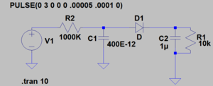
Our circuit is composed of two main parts, an RC circuit and a peak detector. The RC circuit does the actual people detecting. The circuit detects a person because it is fed a square wave with a period roughly equal to four time constants, when someone sits in the circuit they effect the capacitance of it, as the human body has a capacitance of 100-200 pF, and increases the capacitance in the RC circuit, increasing the time constant as well. When the time constant is increased the period of the square wave is not long enough for the capacitor to charge to its peak and so the peak voltage of the circuit is lower when the chair is occupied. The peak detector comes in here to make the measuring the voltage easier. The first part of the peak detector is a diode, which will only let through voltage that is higher than the voltage on the other side of the circuit, therefore if the voltage of the RC circuit is less than the peak voltage it will not be let through. The next element in the peak detector is a parallel RC circuit. In this circuit the capacitor maintains the voltage on the other side of the diode, at the peak voltage, while the resistor slowly drains it, so that when the peak voltage is lowered it is noticed on the other side of the peak detector. Voltage is measured across the parallel RC circuit.
Group Presentation
Communicating Chair to Processer
Solar Power
Server
Interface
To create the interface, we first bought the domain www.librarychair205.com. We then got a third party account at BlueHost, where we could manage our domain. In order to upload code to the domain, it involves creating an FTP account, using Filezilla to upload to that FTP account, using Atom to write code in html so it is compatible with the FTP account, and being able to grab the data from the RaspberryPi server.
Our steps:
- Generate functional HTML code in Atom
- Save the HTML code in index form to be compatible with Firezilla
- Set up the connection between the Firezilla account and the online server's account and IP address
- Upload the FTP file to Bluehost


