Product: ABAQUS/Standard
Transverse shear stress output (TSHR13, TSHR23) and transverse shear section force and section strain output (SF4, SF5, SE4, SE5) for shear-flexible shells.
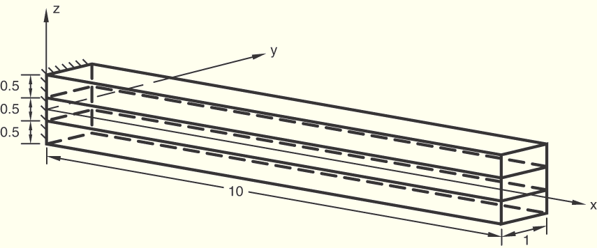
The model consists of a composite plate with a length of 10.0, width of 1.0, and thickness of 1.5. Plane strain conditions are imposed in the y-direction (parallel to the unit width), the end at ![]() 0 is fixed, and various boundary conditions are applied to the remaining degrees of freedom (refer to input files). A single shell element is used to model the plate. The plate has three layers of equal thickness (0.5) defined with the *SHELL SECTION, COMPOSITE or *SHELL GENERAL SECTION, COMPOSITE options. Three integration points are specified in each layer for a total of nine points through the thickness.
0 is fixed, and various boundary conditions are applied to the remaining degrees of freedom (refer to input files). A single shell element is used to model the plate. The plate has three layers of equal thickness (0.5) defined with the *SHELL SECTION, COMPOSITE or *SHELL GENERAL SECTION, COMPOSITE options. Three integration points are specified in each layer for a total of nine points through the thickness.

*ELASTIC, TYPE=LAMINA is used to define an orthotropic material with ![]() 25 × 106,
25 × 106, ![]() 1 × 10⁶,
1 × 10⁶, ![]() 0.25,
0.25, ![]() 0.5 × 10⁶ and
0.5 × 10⁶ and ![]() 0.2 × 10⁶. The material orientation is specified such that the local 1-direction for layers 1 and 3 is parallel to the x-axis, and the local 1-direction for layer 2 is parallel to the y-axis.
0.2 × 10⁶. The material orientation is specified such that the local 1-direction for layers 1 and 3 is parallel to the x-axis, and the local 1-direction for layer 2 is parallel to the y-axis.
A section orientation is used with the *SHELL GENERAL SECTION tests such that the 1-direction is parallel to the y-axis and the 2-direction is parallel and opposite to the x-axis. This section orientation only changes local directions for the section forces and section strains.
Gauss integration is used for the shell cross-section for elements S4, S4R, and S8R.
Two groups of tests are performed; all forces are applied at ![]() 10.
10.
Static tests:
Step 1, uniaxial tension: total force of 20000 in the x-direction.
Step 2, transverse shear: total force of 20000 in the z-direction.
Step 3, pure bending: total moment of 20000 about the y-axis.
Static and dynamics tests:
(The first two static steps are performed to correlate (closely) with the eigenmode results of the frequency step.)
Step 1, static, transverse shear: ![]() 1 at the
1 at the ![]() 10 edge.
10 edge.
Step 2, static, uniaxial tension: ![]() 1 at the
1 at the ![]() 10 edge.
10 edge.
Step 3, frequency: extract four lowest eigenmodes.
Step 4, steady-state dynamics: total force of 20000 in the z-direction.
Step 5, steady-state dynamics, direct: total force of 20000 in the z-direction.
Step 6, modal dynamic: total force of 20000 in the z-direction.
Step 7, response spectrum.
The verification of the transverse shear results is based on the formulation described in “Transverse shear stiffness in composite shells and offsets from the midsurface,” Section 3.6.8 of the ABAQUS Theory Manual.
The *EL FILE, DIRECTIONS=YES option is used in the input files esf4sct2.inp, esf4slt2.inp, and ese4slt2.inp.
S4 elements, static steps, *SHELL SECTION, COMPOSITE.
S4 elements, static, frequency, steady-state dynamics, modal dynamic, and response spectrum steps, *SHELL SECTION, COMPOSITE.
S4 elements, static, frequency, steady-state dynamics, modal dynamic, and response spectrum steps with *SHELL GENERAL SECTION, COMPOSITE.
S4R elements, static steps, *SHELL SECTION, COMPOSITE.
S4R elements, static, frequency, steady-state dynamics, modal dynamic, and response spectrum steps, *SHELL SECTION, COMPOSITE.
S4R elements, static, frequency, steady-state dynamics, modal dynamic, and response spectrum steps with *SHELL GENERAL SECTION, COMPOSITE.
S8R elements, static steps, *SHELL SECTION, COMPOSITE.
S8R elements, static, frequency, steady-state dynamics, modal dynamic, and response spectrum steps, *SHELL SECTION, COMPOSITE.
S8R elements, static, frequency, steady-state dynamics, modal dynamic, and response spectrum steps with *SHELL GENERAL SECTION, COMPOSITE.
S8RT elements, coupled temperature-displacement steps with static loading, *SHELL SECTION, COMPOSITE.