Use dimensions between lines and vertices to define and maintain dimensional relationships between features. Dimensions can be applied between lines and vertices from any of the following:
Sketch geometry
Reference geometry
Construction geometry

Create a part consisting of only the shell.
Extrude a solid feature from the face of the shell (the circular post).

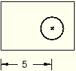
If you move either the left or the right edge of the shell, the distance between the center of the circle and the left edge remains constant, as shown in the following figure:

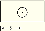
If you want to keep the post centered between the left and right edges of the shell, you must add two dimensions and associate them with parameters. You can then define a parametric equation, dim2=(dim1)/2, to set the distance from the left edge to the post at half the width of the shell, as shown in the following figure:

Note: The distance dimension associated with the parameter dim1 is defined in the sketch of the shell feature and cannot be edited in the sketch of the post. When you dimension reference geometry, ABAQUS/CAE colors the dimension magenta to indicate an overconstraint. To clear the overconstraint, you must make dim1 a reference dimension. ABAQUS/CAE places parentheses around the value of reference dimensions (or around the parameter name if the dimension is associated with a parameter) and automatically updates their values if the dimensioned quantity changes. For more information, see “Editing dimensions,” Section 19.13.
You can modify any dimension or parameter in a sketch. For detailed instructions, see “Editing dimensions,” Section 19.13, and “Adding and editing parameters,” Section 19.12.5, respectively.