
You can control the shape of the elements in your mesh by selecting Mesh![]() Controls from the main menu bar. The Element Shape options are located at the top of the Mesh Controls dialog box that appears.
Controls from the main menu bar. The Element Shape options are located at the top of the Mesh Controls dialog box that appears.
To specify the element shape to be used in a region:
From the main menu bar, select Mesh![]() Controls.
Controls.
ABAQUS/CAE displays prompts in the prompt area to guide you through the procedure.
Tip:
You can set the element shape using the ![]() tool, located in the Mesh module toolbox.
tool, located in the Mesh module toolbox.
If your part or assembly contains more than one region, select those regions whose element shapes you want to view or modify and then press mouse button 2. All the selected regions must have the same dimensionality.
The Mesh Controls dialog box appears.
From the list of Element Shape options, select the element shape of your choice.
If you selected a two-dimensional region, you can choose from the following element shape options:
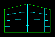
Quad
Use exclusively quadrilateral elements; do not use any triangles. This setting is the default. The following figure shows an example of a mesh that was constructed using this setting:
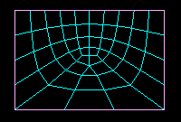
Quad-dominated
Use primarily quadrilateral elements, but allow triangles in transition regions. The following figure shows an example of a mesh that was constructed using this setting:
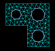
Tri
Use exclusively triangular elements. The following figure shows an example of a mesh that was constructed using this setting:
If you selected a three-dimensional region, you can choose from the following element shape options:
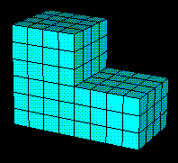
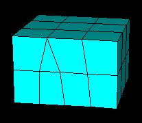
Hex
Use exclusively hexahedral elements; do not use any triangular prisms (wedges). This setting is the default. The following figure shows an example of a mesh that was constructed using this setting:
Hex-dominated
Use primarily hexahedral elements, but allow some triangular prisms in transition regions. The following figure shows an example of a mesh that was constructed using this setting:
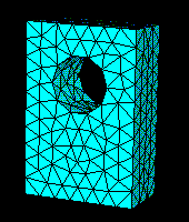
Tet
Use exclusively tetrahedral elements. The following figure shows an example of a mesh that was constructed using this setting:
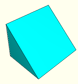
Wedge
Use exclusively wedge elements. The following figure shows an example of a single-element mesh that was constructed using this setting:
Click OK.
The next time you generate a mesh on the selected regions, your selections will be honored.
If the selected regions are already meshed, you will be prompted to delete the mesh or to cancel the entire procedure.
