Products: ABAQUS/Standard ABAQUS/CAE
Acoustic interface elements:
can be used to couple a model of an acoustic fluid to a structural model containing continuum or structural elements;
couple the accelerations of the surface of the structural model to the pressure in the acoustic medium;
can be used in dynamic and steady-state dynamic procedures;
must be defined with the nodes shared by the acoustic elements and the structural (or solid) elements;
can be used only in small-displacement simulations and are not intended for use in nonlinear or hydrostatic fluid-structure interactions;
are ignored in eigenfrequency extraction analyses if the subspace iteration eigensolver is used; and
if necessary, can be degenerated into triangular elements.
The acoustic interface elements are used in simulations where the motion of a solid structure influences the pressure in the acoustic fluid, such as when the vibrations of a car frame produce noise in the passenger compartment; or where the pressure in the fluid affects a neighboring structure, such as when the small-amplitude sloshing of a fluid inside a container affects its response.
User-specified acoustic interface elements are also useful in problems involving only an acoustic medium because they allow you to specify displacement, velocity, or acceleration boundary conditions directly on the nodes of the acoustic interface elements. In this application, however, you must be aware that the tangential displacements are not coupled to the fluid. Therefore, zero-energy modes may arise involving the displacement degrees of freedom if these nodes are not constrained in the tangential direction. When acoustic interface elements are used to couple fluid and solid elements, this problem does not arise because of the stiffness and inertia of the solid.
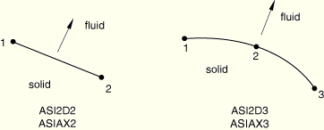
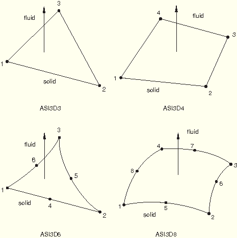
The order of the underlying acoustic and structural elements usually dictates which acoustic interface element should be used. The general acoustic interface element, ASI1, can be used in any coupled acoustic-structural simulation; however, normally it is used only with the acoustic link elements (AC1D2 and AC1D3).
The connectivity of the acoustic interface elements and the right-hand rule define the normal direction of the acoustic-structural interface, as shown in “Acoustic interface element library,” Section 26.14.2. It is very important that this normal point into the acoustic fluid. The one exception is the ASI1 acoustic interface element, where you must define the normal direction.
You must associate the acoustic interface section definition with a set of acoustic interface elements. This section definition must be used with three-dimensional and axisymmetric acoustic interface elements, even though there are no user-defined geometric properties for these elements.
| Input File Usage: | *INTERFACE, ELSET=element_set_name |
| ABAQUS/CAE Usage: | Property module: |
The ASI1 elements consist of a single node. ABAQUS/Standard cannot calculate the surface area associated with these elements, so you must supply this information. If accurate surface areas are not given, ABAQUS/Standard may calculate incorrect accelerations or acoustic fluid pressure at the acoustic-structural interface.
In addition, ABAQUS/Standard cannot calculate the direction of the interface normal associated with these elements. You must provide the direction cosines, in the global Cartesian coordinate system, of the interface normal for these elements.
| Input File Usage: | *INTERFACE surface area, X-direction cosine, Y-direction cosine, Z-direction cosine |
| ABAQUS/CAE Usage: | General-use acoustic interface sections are not supported in ABAQUS/CAE. |
You can specify the thickness of planar acoustic interface elements. The default value is unit thickness.
| Input File Usage: | *INTERFACE thickness |
| ABAQUS/CAE Usage: | Property module: Create Section: select Other as the section Category and Acoustic interface as the section Type: Plane stress/strain thickness: thickness |
It is normally assumed that the same order of interpolation will be used for both the acoustic fluid mesh and the structural mesh (at least at the interface surfaces). If this is not the case, suitable MPCs must be applied to the nodes along the acoustic-structural interface to maintain the compatibility in the pressure (MPC type P LINEAR) or displacement fields (MPC type LINEAR).