Products: ABAQUS/Explicit ABAQUS/CAE
An integrated output section:
can be two-dimensional or three-dimensional;
can be used to track the average motion of a surface;
can be used in association with integrated output requests to study the “force-flow” in the model; and
does not impose any constraint on the motion of the surface.
An integrated output section is a way to associate a surface with a coordinate system and/or a reference node for one or both of the following purposes:
tracking the average motion of the surface; and/or
expressing the force and the moment transmitted through the surface in a local coordinate system, with the moment taken about a point that moves with the surface.
The average motion of a surface can be obtained as the displacement and/or rotation history at the reference node on an integrated output section definition. You must define a reference node that is not connected to any other part of the finite element model and select whether the reference node follows only the average translation of the surface or both the translation and the rotation. Since the reference node is not connected to the rest of the model, an integrated output section definition used to track the average surface motion does not form a constraint on the motion of any nodes in the model.
The “force-flow” in a complicated model can be studied using integrated output sections defined over a number of interior cross-section-like surfaces cutting through various parts of the model. It can be equally useful to sum forces over an exterior surface in contact or to sum forces transmitted through a tie constraint between surfaces, which is done by associating an integrated output section definition with an integrated output request. The vector output quantities can be expressed in a coordinate system of choice by specifying an orientation on an integrated output section definition. This coordinate system can rotate by an amount given by the rotational degrees of freedom at the reference node. In addition, the output of the integrated moment across the surface can be taken about a location that can translate by an amount given by the translational degrees of freedom at the reference node. Integrated output over a given surface can be requested with different coordinate systems and reference nodes by employing multiple integrated output section definitions over the same surface.
You must assign a name to each integrated output section. This name is used to associate the section with an integrated output request. In addition, you must identify the surface over which the section is being defined (see “Defining element-based surfaces,” Section 2.3.2).
| Input File Usage: | *INTEGRATED OUTPUT SECTION, NAME=section_name, SURFACE=surface_name |
| ABAQUS/CAE Usage: | Step module: Output |
To study the “force-flow” through various paths in a model, you must create interior surfaces that cut through one or more regions (similar to a cross-section) so that you can request integrated output of the total force and moment transmitted across these surfaces. You can create such interior surfaces over the element facets, edges, or ends by simply cutting through one or more regions of the model with a plane; see “Creating interior cross-section surfaces” in “Defining element-based surfaces,” Section 2.3.2, for more information.
A reference node can be associated with an integrated output section for one or both of the following purposes:
tracking the average motion of the surface; and/or
computing the variables from an integrated output request in a coordinate system that moves with the motion of the reference node.
When an integrated output section with a reference node is associated with an integrated output request, the total moment transmitted through the section is computed with respect to the current location of the reference node. If the reference node has active rotational degrees of freedom, the coordinate system used to express the integrated output variables rotates with the rotation of the reference node.
The reference node can be repositioned automatically at the center of the surface in the initial configuration when the reference node is not connected to the rest of the model.
The default is to leave the reference node in its specified position.
| Input File Usage: | Use the following option to position the reference node at the center of the surface: |
*INTEGRATED OUTPUT SECTION, REF NODE=n, POSITION=CENTER |
| ABAQUS/CAE Usage: | Step module: integrated output section editor: Anchor at reference point: Edit: select reference point: Move point to center of surface |
It is often meaningful to obtain integrated output over a surface using a coordinate system and a point that moves with the average surface motion. When the reference node is not connected to the rest of the model, it can be specified to translate with the average translation of the surface without any rotation or to both translate and rotate with the average motion of the surface.
By default, the reference node does not track the average motion of the surface.
| Input File Usage: | Use the following option if the reference node must translate with the average translation of the surface: |
*INTEGRATED OUTPUT SECTION, REF NODE=n,
REF NODE MOTION=AVERAGE TRANSLATION
Use the following option if the reference node must both translate and rotate with the average translation of the surface: *INTEGRATED OUTPUT SECTION, REF NODE=n, REF NODE MOTION=AVERAGE |
| ABAQUS/CAE Usage: | Step module: integrated output section editor: Anchor at reference point: Edit: select reference point: Point motion: Average translation and rotation or Average translation |
You can define a local coordinate system on an integrated output section and associate the section with an integrated output request to express the integrated output variables in the local coordinate system. You can specify an orientation as the local coordinate system and, possibly, further project it onto the surface. Alternatively, you can form a local coordinate system by projecting the global coordinate system onto the surface following the ABAQUS conventions (see “Conventions,” Section 1.2.2). If a local system is not defined explicitly, the local system is initialized to the global coordinate system.
The initial coordinate system, whether explicitly defined or initialized to the global coordinate system, will rotate with the deformation if a reference node is specified and that reference node has active rotational degrees of freedom. If the reference node is not connected to the rest of the model and its motion is based on both the average translation and rotation of the surface, the rotational and translational degrees of freedom are activated at the reference node.
| Input File Usage: | Use the following option to define the initial coordinate system for the section: |
*INTEGRATED OUTPUT SECTION, ORIENTATION=orientation_name |
| ABAQUS/CAE Usage: | Step module: integrated output section editor: CSYS: Edit: select orientation |
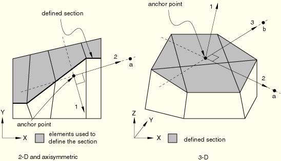
Either the coordinate system defined by the specified orientation or the global coordinate system can be projected onto the section surface to obtain a local coordinate system. Projection onto the surface is based on the average normal of the surface; the local 1-direction is formed perpendicular to the surface (see Figure 2.5.1–1).
| Input File Usage: | Use the following option to project the coordinate system onto the section surface: |
*INTEGRATED OUTPUT SECTION, PROJECT ORIENTATION=YES |
| ABAQUS/CAE Usage: | Step module: integrated output section editor: Project orientation onto surface |
An integrated output request is used to obtain history output of variables such as total force transmitted across a surface (see “Integrated output in ABAQUS/Explicit” in “Output to the output database,” Section 4.1.3). Such a request may refer to an integrated output section definition to identify the surface where output is needed and to provide a local coordinate system and/or a reference node as a point about which the total moment across the surface is computed.
| Input File Usage: | Use both of the following options to associate an integrated output section with an integrated output request: |
*INTEGRATED OUTPUT SECTION, NAME=section_name *INTEGRATED OUTPUT, SECTION=section_name |
| ABAQUS/CAE Usage: | Step module: |
Output History output request editor: Domain: Integrated output section: section_name |
Integrated output sections are subject to the following limitations:
The surface associated with an integrated output section cannot be an analytical rigid surface.
The surface associated with an integrated output section can contain facets over rigid or axisymmetric elements. However, such an integrated output section cannot be associated with an integrated output request (see “Output to the output database,” Section 4.1.3).