LED control with Button + Arduino
Initially, we were going to use nifty buttons with built-in LEDs to indicate that the system was on and running, but unfortunately we found that the leads for the LED part of the button were super flimsy and would turn would break easily upon soldering. So we had to think creatively to come up with another to indicate to the user that the system was turned on in the interface, so we turned our attention to the row of LEDs already being used to indicate the heat level of the pads. With quite a bit of ease, we were able to have them blink in fun sequence in response to the button being pressed. Now, allow us to teach you how to do the same!
Materials: Arduino Mega board, Tactile pushbutton (easily found on Sparkfun), one 10kΩ resistor, four 220Ω resistors, 4 LEDs, wires
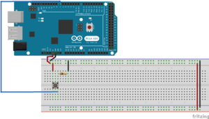
Step 1: Connect the button. This we took directly from Arduino’s tutorial, which can be found here (the resistor seen is a 10kohm resistor). The placement of the button pin is up to you, as long as it is connected to a digital pin.
Step 2: Now time for the coding! It is a very simple bit of code, which is can be found here. Read through the comments to get a full understanding of it, and make sure that the declaration of buttonPin matches the digital pin on the Arduino that your button is connected to.
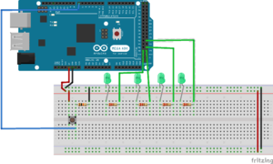
Step 3: Now that the button is connected to the board, it is time to add our LED lights, along with their resistors. For our project, we used 4, as seen in the circuit diagram.
Make sure that at the end of each LED resistor, a wire runs from a pin parallel to the resistor lead and into a digital pin on the Arduino Mega.
Step 4: More code! You can find it here, but we are really just building off the original button code, only with a couple additions:
- Initialization of the LEDs onto the Arduino (same as for the button)
- Declaring the LEDs as “Outputs” in the void setup (as the button is declared as an Input)
- Including a for loop inside the if statement portion in which the button and system are turned on.
- Once the for loop conditions are set, the blinking sequence is really up to you. Just write “digitalWrite(led_, HIGH) to turn the LED of your choice on, and add a very small delay in between the next course of action
- Also make sure to include “digitalWrite(led_, LOW)” for each LED under the else if condition where the system is off, just to ensure that every light is off when the system is off
And that’s it - go blink away!

